Table of Contents
Advertisement
Quick Links
INSTALLATION MANUAL
AIR
CONDITIONER
Please read this installation manual completely before installing the product.
Installation work must be performed in accordance with the national wiring
standards by authorized personnel only.
Please retain this installation manual for future reference after reading it
thoroughly.
Ceiling Concealed Duct
P/NO: MFL67939944
Copyright © 2020 LG Electronics Inc. All Rights Reserved
www.lg.com
Advertisement
Table of Contents

Related Manuals for LG ABNW24GM1E4


Summary of Contents for LG ABNW24GM1E4
- Page 1 Installation work must be performed in accordance with the national wiring standards by authorized personnel only. Please retain this installation manual for future reference after reading it thoroughly. Ceiling Concealed Duct www.lg.com P/NO: MFL67939944 Copyright © 2020 LG Electronics Inc. All Rights Reserved...
-
Page 2: Table Of Contents
TABLE OF CONTENTS TABLE OF CONTENTS TIPS FOR SAVING EN ERGY IMPORTANT SAFETY IN STRUCTIONS INTRODUCTION Features INSTALLATION OF IN DOOR Selection of the best location Installation of Unit Indoor Unit Drain Piping Drain test Thermal Insulation Wiring Connection INSTALLATION INSTRUCTION Remote controller installation Group control Installer Setting - How to Enter Setting Mode... -
Page 3: Tips For Saving Energy
TIPS FOR SAVING ENRGY TIPS FOR SAVING ENERGY Here are some tips that will help you minimize the power consumption when you use the air conditioner. You can use your air conditioner more efficiently by referring to the instructions below: •... -
Page 4: Important Safety Instructions
IMPORTANT SAFETY INSTRUCTION IMPORTANT SAFETY INSTRUCTIONS READ ALL INSTRUCTIONS BEFORE USING THE APPLIANCE. Always comply with the following precautions to avoid dangerous situations and ensure peak performance of your product WARNING It can result in serious injury or death when the directions are ignored CAUTION It can result in minor injury or product damage when the directions are ignored WARNING... - Page 5 IMPORTANT SAFETY INSTRUCTION • Make sure that a separate power supply circuit is provided for this unit and that all electrical work is carried out by qualified personnel according to local laws and regulations and this installation manual. An insufficient power supply capacity or improper electrical construction may lead to electric shocks or fire. •...
-
Page 6: Introduction
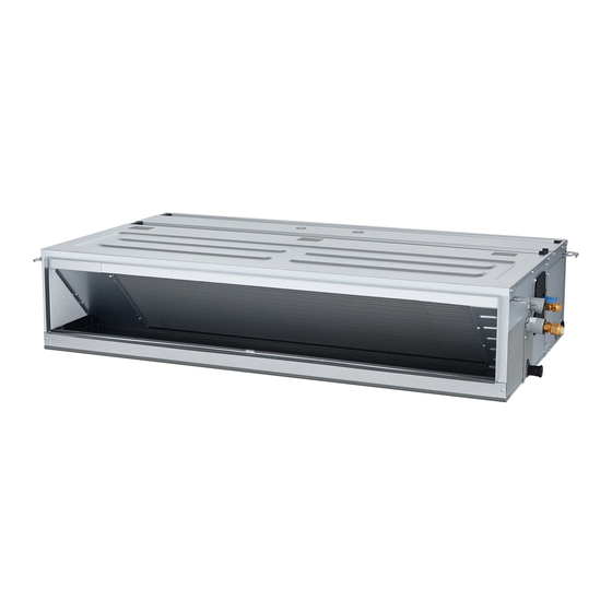
INTODUCTION INTRODUCTION Features Air inlet vents Air outlet vents Remote Controller... -
Page 7: Installation Of Indoor
INSTALLATION OF INDOOR INSTALLATION OF INDOOR Selection of the best location Installation of Unit - The place shall easily bear a load exceeding Install the unit above the ceiling correctly. four times the indoor unit’s weight. - The place shall be able to inspect the unit as CASE 1 the figure. - Page 8 INSTALLATION OF INDOOR - Select and mark the position for fixing bolts. CASE 2 - Drill the hole for set anchor on the face of - Install the unit leaning to a drainage hole side ceiling. as a figure for easy water drainage. Position of console Bolt - A place where the unit will be leveled and that can support the weight of the unit.
- Page 9 INSTALLATION OF INDOOR CAUTION • Install declination of the indoor unit is very important for the drain of the duct type air condi- tioner. • Minimum thickness of the insulation for the connecting pipe shall be 5mm. Front of view •...
-
Page 10: Indoor Unit Drain Piping
INSTALLATION OF INDOOR Indoor Unit Drain Piping Drain test - Drain piping must have down-slope (1/50 to - Connect the main drain pipe to the exterior 1/100): be sure not to provide up-and-down and leave it provisionally until the test comes slope to prevent reversal flow. -
Page 11: Thermal Insulation
INSTALLATION OF INDOOR Thermal Insulation - Loosen the flare nut of the indoor unit's piping connection port, insert it into the liquid pipe and the gas pipe, and then conduct flaring work on the ends of each pipe. - Insulate each of the liquid pipes and gas pipes using insulation material for piping. Ⓐ... -
Page 12: Wiring Connection
INSTALLATION OF INDOOR Wiring Connection - Remove the control box cover for electrical connection between the indoor and outdoor - Open the control box cover and connect the unit. (Remove screws ①.) Remote controller cable and Indoor power wires. - Use the cord clamper to fix the cable. Control terminal board Control box Control box cover... -
Page 13: Installation Instruction
INSTALLATION INSTRUCTION INSTALLATION INSTRUCTION Please install the wired controller mounting plate to the position you want with the screws provided. - Do not bend the mounting plate during installation, as it may cause poor fixing. Please install a wired controller with a mounting box (if any) properly. (The installation box shall be type 86) Installation box (type 86) - Page 14 Side Side 12 V Black CAUTION Remove remote controller by inserting a • Specification of LG supplied extension screwdriver into the lower separating holes cable: AWG#22, 3 core shielded. and twisting to release the controller from (Model : PZCWRC1) backplate.
- Page 15 INSTALLATION INSTRUCTION CAUTION • When installing the wired remote con- troller, do not bury it in the wall. (It can cause damage in the temperature sen- sor.) • Do not install the cable to be 164 ft(50 m) or longer. (It can cause communication error.) - When connecting Terminal Blocks of the Remote...
-
Page 16: Remote Controller Installation
INSTALLATION INSTRUCTION Remote controller installation Since the room temperature sensor is in the remote controller, the remote controller box should be installed in a place away from direct sunlight, high humidity and direct supply of cold air to maintain proper space temperature. Install the remote controller about 5 ft(1.5 m) above the floor in an area with good air circulation at an average temperature. -
Page 17: Group Control
INSTALLATION INSTRUCTION Group Control * When installing 2 remote controllers to one indoor unit with event communica- When installing more than 2 units of air tion function, set the master/slave of the conditioner to one wired remote controller, remote controller. (Refer to remote con- please connect as the right figure. - Page 18 INSTALLATION INSTRUCTION How to enter the setting mode Caution The installation setting mode is used for detailed function settings of the wired controller. The incorrect setting mode may cause product failure or loss of body or property of the user. The setting must be performed by a person with professional qualification. The company does not assume responsibility for installation or modification by unprofessional personnel, or does not provide free repair services.
- Page 19 INSTALLATION INSTRUCTION Installer Setting - Central Control Address Setting This function is used to connect to the central control. Please refer to the central controller manual for details. Pressing the key and simultaneously for more than 3 seconds can enter the manual setting mode of the system. - After entering the manual setting mode, press the key to select the code value for...
-
Page 20: Installer Setting - Wired Controller Master / Slave Setting
INSTALLATION INSTRUCTION Installer Setting - Wired Controller Master / Slave Setting This function is used for group control or setting when two wired controllers are used. Pressing the key and simultaneously for more than 3 seconds can enter the manual setting mode of the system. - Select the master / slave setting code of the wired controller by pressing the mode button after entering the manual setting mode. -
Page 21: Installer Setting - Static Pressure Step Setting
INSTALLATION INSTRUCTION Installer Setting - Static Pressure Step Setting This function is only applicable to products with hidden ducts. Setting this function on other products will cause malfunction. This function is only available for some of models. This function divides the static pressure setting of the product into 11 steps. Pressing the key and simultaneously for more than 3 seconds can... -
Page 22: Installer Setting - Static Pressure Setting
INSTALLATION INSTRUCTION Installer Setting - Static Pressure Setting This function is only available for products with hidden air ducts. Setting this function in other types of products will cause a malfunction. Pressing the key and simultaneously for more than 3 seconds can enter the manual setting mode of the system. -
Page 23: Installer Setting - E.s.p
INSTALLATION INSTRUCTION Installer Setting - E.S.P Setting This is a function to set wind speeds and volumes. This feature is to facilitate installation. • Incorrect set of external static pressure may cause malfunction of the air conditioner. • The external static pressure setting must be performed by qualified personnel. Pressing the key and simultaneously for more than 3 seconds can... -
Page 24: Installer Setting - Thermistor
INSTALLATION INSTRUCTION Settings - temperature Installer Setting - Thermistor This function is to test the room temperature by selecting a temperature sensor. Pressing the key and simultaneously for more than 3 seconds can enter the manual setting mode of the system. - After entering the manual setting mode, select the setting code of the temperature sensor by pressing... -
Page 25: Installer Setting - Test Run Mode
INSTALLATION INSTRUCTION Settings - trial run Installer Setting - Test Run Mode The test mode must be run after installation. Please refer to the product manual for details on operation. Pressing the key and simultaneously for more than 3 seconds can enter the manual setting mode of the system. -
Page 26: Installer Setting - Celsius Setting
INSTALLATION INSTRUCTION Installer Setting - Celsius Setting Settings - celsius settings This function is used to set the unit for changing Celsius as 1 ℃ or 0.5 ℃. Pressing the key and simultaneously for more than 3 seconds can enter the manual setting mode. - When entering the manual setting mode, press the mode button to select the Celsius setting code value. - Page 27 INSTALLATION INSTRUCTION Saudi Models [Table. 1] Static Pressure[mmAq(Pa)] 2.5(25) 4(39) 5(49) 6(59) 8(78) 9(88) 10(98) 11(108) 12(118) 13(127) 14(137) Capacity - Phase Step CMM Setting Value (Heating/Cooling) 32 : 01 32 : 02 32 : 03 32 : 04 32 : 05 32 : 06 32 : 07 32 : 08 32 : 09 32 : 10 32 : 11 HIGH 60k (54k) - 1Ф...
- Page 28 INSTALLATION INSTRUCTION Static Pressure[mmAq(Pa)] 2(20) 2.5(25) 3(29) 4(39) 5(49) 6(59) 7(69) 8(78) 9(88) 10(98) Capacity - Phase Step Setting Value (Heating/Cooling) 32 : 01 32 : 02 32 : 03 32 : 04 32 : 05 32 : 06 32 : 07 32 : 08 32 : 09 32 : 10 HIGH 30k - 1Ф...
- Page 29 INSTALLATION INSTRUCTION NOTE * If it is zero static pressure, please set value below Maximum value. Capacity - Phase Maximum Value (Heating/Cooling) 60k (54k) - 1Ф 60k (54k) - 3Ф 48k - 1Ф 42k - 1Ф 36k - 1Ф 30k - 1Ф 24k - 1Ф...
- Page 30 8(78) 10(98) 12(118) 13(127) 14(137) 15(147) Step Model Setting Value 32:01 32:02 32:03 32:04 32:05 32:06 32:10 32:11 32:07 32:08 32:09 HIGH 16.5 14.5 ABNW24GM1E4 HIGH ABNW30GM1E4 16.5 14.5 Static Pressure[mmAq(Pa)] 2(20) 2.5(25) 3(29) 4(39) 5(49) 6(59) 7(69) 8(78) 9(88) 10(98)
- Page 31 INSTALLATION INSTRUCTION Bahrain Models [Table. 3] Static Pressure[mmAq(Pa)] 2.5(25) 4(39) 5(49) 6(59) 8(78) 9(88) 10(98) 11(108) 12(118) 13(127) 14(137) Capacity - Phase Step CMM Setting Value 32 : 01 32 : 02 32 : 03 32 : 04 32 : 05 32 : 06 32 : 07 32 : 08 32 : 09 32 : 10 32 : 11 HIGH 50 60k (54k) - 1Ф...
- Page 32 INSTALLATION INSTRUCTION Static Pressure[mmAq(Pa)] 2(20) 2.5(25) 3(29) 4(39) 6(59) 8(78) 10(98) 12(118) 13(127) 14(137) 15(147) Capacity - Step Phase Setting Value 32:01 32:02 32:03 32:04 32:05 32:06 32:10 32:11 32:07 32:08 32:09 HIGH 16.5 14.5 18k - 1Ф HIGH 24k - 1Ф 16.5 14.5 NOTE...
-
Page 33: Dip Switch Setting
INSTALLATION INSTRUCTION NOTE * If it is zero static pressure, please set value below Maximum value. Capacity - Maximum Value Phase 60k (54k) - 1Ф 60k (54k) - 3Ф 48k - 1Ф 48k - 3Ф 42k - 1Ф 36k - 1Ф 30k - 1Ф...
Need help?
Do you have a question about the ABNW24GM1E4 and is the answer not in the manual?
Questions and answers