Advertisement
WARNINGS
• TO AVOID FIRE, SHOCK, OR DEATH; TURN OFF POWER AT CIRCUIT
BREAKER OR FUSE AND TEST THAT POWER IS OFF BEFORE WIRING!
• To be installed and/or used in accordance with appropriate electrical codes
and regulations.
• If you are unsure about any part of these instructions, consult an electrician.
Before Installation
• Install into any single gang device back box.
• Support Multi-gang installations.
• Require Decora
faceplate, sold separately.
®
• Devices use 0-10Vdc low voltage control wires which may be installed as Class 1 or Class 2.
IMPORTANT NOTE: If installed as Class 2, all devices in the circuit must be Class 2 rated and this switch must be wired per instructions below.
Class 2 Installation:
As required under NEC code NFPA 70, paragraph 725.136 (d) and under Canadian Electrical Code, section 16-202, the Class 2 0-10V (pink and violet)
control wires must be mechanically separated from Class 1 wiring (line, neutral and ground power lines) when located within the same electrical box.
This is accomplished by installing a mechanical barrier such as silicone tubing or other non-conducting sleeve over the length of 0-10V control wires.
When product is used with 120VAC power source and the 0-10V control wires are connected to CL3, CL3R or CL3P rated control cables (or permitted
substitute), then silicone tubing or other non-conducting sleeve is required over the control wires for the entire wire length from the device to the location
where the wires exit the box. Tubing is not required on the CL3, CL3R or CL3P between the wire connector and extending out of the electrical box.
When used with 277VAC power source and the 0-10V control wires are connected to CL3, CL3R or CL3P rated control cables (or permitted substitute),
then silicone tubing or other non-conducting sleeve is required over the control wires for the entire wire length from the device to the location where the
wires exit the box. Tubing is also required on the CL3, CL3R or CL3P between the wire connector and extending out of the electrical box.
NOTE:
• Silicone tubing should be NRTL (UL/CSA/ETL) recognized or equivalent to provide mechanical separation equal to .25" in air.
• Connectors joining 0-10V control wires should be approved LISTED CONNECTORS.
• Wire connectors and wire tubing should be provided by the installation contractor.
Installation
WARNING: TO AVOID FIRE, SHOCK, OR DEATH;
TURN OFF POWER at circuit breaker or fuse and
test that power is off before wiring!
1.
Strip wires 3/4" and connect as per wiring diagram.
exposed copper.
2.
Gently place the wires and your device into the wall box and attach
with screws provided.
3.
Restore power and test ON/OFF operation. LED locator light should
be ON when switch power is turned OFF.
4.
If desired, change switch color.
5.
Install Decora faceplate.
© 2022 Leviton Mfg. Co., Inc.
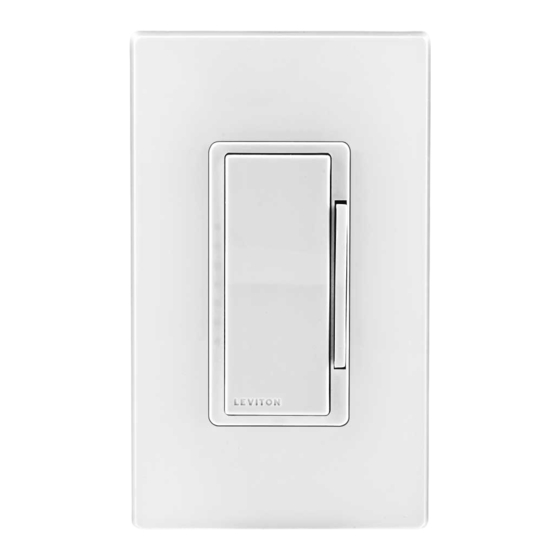
0-10VDC RF Wall Dimmer
Cat. No. ZS057-D0Z, Ratings: 120-277VAC, 50/60Hz.
Cat. No. ZS057-30Z, Ratings: 347VAC, 50/60Hz.
INSTALLATION INSTRUCTIONS
Electrical Box
Hot (Black)
Line
Neutral (White)
CAUTIONS
• Use this device with copper or copper clad wire only.
• For indoor applications only.
• Save these instructions.
• To avoid damage to the product, DO NOT use disinfecting products,
including foggers, sprays or other types of atomized cleaning
agents. DO NOT spray liquid onto the product. To clean use a
damp cloth with mild soap.
Connectors
Black
Blue
White
Green
Ground
NOTE: Depending on date of manufacture, the pink 0-10V wire may be gray
Class 1 installation shown (for Class 2, refer to notes)
White
Blue
Black
Green
Violet
Pink
To release, push sides.
DI-000-ZS057-02C
ENGLISH
Violet
Pink
Sleeve
Black
0-10 VDC
White
Ballast/LED Driver
Load
Neutral
Line (Hot)
Ground
Line up and press in to attach.
DI-000-ZS057-02C
Advertisement
Table of Contents

Related Manuals for Leviton lumina 0-10VDC


Summary of Contents for Leviton lumina 0-10VDC
- Page 1 ON when switch power is turned OFF. Black Line (Hot) Green Ground Violet Pink If desired, change switch color. Install Decora faceplate. To release, push sides. Line up and press in to attach. © 2022 Leviton Mfg. Co., Inc. DI-000-ZS057-02C...
- Page 2 LIMITED 2 YEAR WARRANTY AND EXCLUSIONS Leviton warrants to the original consumer purchaser and not for the benefit of anyone else that this product at the time of its sale by Leviton is free of defects in materials and workmanship under normal and proper use for two years from the purchase date.
Need help?
Do you have a question about the lumina 0-10VDC and is the answer not in the manual?
Questions and answers