
Related Manuals for Edin Univox PLS-X1


Summary of Contents for Edin Univox PLS-X1
- Page 1 Univox® PLS-X1-5 Induction Loop Drivers Installation Guide Univox® PLS-X1 Part No 217100 Univox® PLS-X3 Part No 217300 Univox® PLS-X5 Part No 217500...
-
Page 2: Table Of Contents
Content Introduction ........................4 Package contents ......................4 Connections and controls ..................... 5 1. Input level control ..................... 6 2. Input level LEDs....................6 3-4. Parametric MLC ....................6 5. System Diagnostics .................... 7 6. Loop Current Control ..................7 7. - Page 3 Prepare installation .....................14 Planning ........................14 Tools required......................14 Loop cable ......................14 Placement of the driver ..................15 Placement of the microphones ................15 Maximum recommended segment size (to comply with IEC 60118-4) ...15 Installation ........................16 Start-up procedure ......................16 Input connection and adjustments ................16 Output connection and adjustments ...............17 Metal Loss Correction frequency setting ..............18 MLC function in maximum position ................18...
-
Page 4: Introduction
Introduction Thank you for choosing Univox. The new Univox PLS-X series loop drivers combine 50 years of experience with the latest ® in electronic design to deliver unrivaled sound clarity, power and performance in a compact stylish housing. Our Engineering Simplicity philosophy is evident in the functionality and ease of use of each model. -
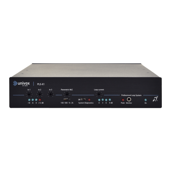
Page 5: Connections And Controls
Connections and controls PLS-X5 In 1 In 2 In 3 Parametric MLC Loop current Professional Loop System 0 +12 dB 100 500 1k 2k System Diagnostics 9 dB Clip Monitor 8. 9. Input 3 Input 2 Input 1 Out Pre PUSH In Pow www.univox.eu... -
Page 6: Input Level Control
Explanation Note Univox PLS-X series is only working if a loop cable is connected. If no loop cable is con- nected, the Peak indicator is lit constantly as a warning. All controls are regulated with a small screw driver. 1. Input level control (In1-In3) Each input can be set to the correct input level using the appropriate single turn potentiometer on the front panel. -
Page 7: System Diagnostics
5. System diagnostics Univox PLS-X series has a built-in system test. We recommend that this feature is used periodically, at least monthly, to check the integrity of the loop driver, its inputs and the loop condition. To access the system diagnostics mode, set the switch on the front panel to the right. All the inputs are now disabled and an internal 1kHz oscillator is connected to the input instead. -
Page 8: Voltage Clipping/Peak Led
8. Voltage clipping/Peak LED The Peak LED will illuminate when the voltage is clipping, i.e. there is insufficient voltage to maintain a constant current. Momentary short term voltage clipping is unlikely to be audible in hearing aids, but if clipping occurs for any length of time (the Clip LED (8) remains on), the audio quality will suffer and remedial action should be taken to reduce or eliminate the problem. -
Page 9: Loop Terminals
The units are designed to run 24/7. They do not have a separate on/off switch and can only be turned off by disconnecting or turning off the power supply. 11. Loop terminals The two outer terminals (screw 1 and 4) are used for connecting a single turn loop. The two inner centre terminals (screw 2 and 3) provide a shorting bar to couple a 2-turn loop when a twin core cable is used (see page 14). -
Page 10: Remote Output Monitor Connector (Screw 5+6)
16. Remote output monitor connector (screw 5+6) A LED connected to this terminal will mirror the operation of the 0dB output current Level LED on the front panel, thus allowing the monitoring of the presence of output current in a more convenient location. -
Page 11: Input 3
20. Input 3 Input 3 Input 3 is an unbalanced line input. The sensitivity is adjusted using the control on the front panel. The source may be connected using the RCA connector (L/R) or the Phoenix screw terminal, but can't be used simultaneously. If the RCA input is used: Mono signals are connected through R or L and the earth connection. -
Page 12: Override On/Off Dip Switch 4
Note The DIP switches should be set in the appropriate position before connecting the input signal to avoid causing damage to the input. 24. Override On/Off (DIP switch 4) Input 2 With the DIP switch in ‘down’ position, Input 2 is set as the Priority Input. In this case, when a signal is detected, all other inputs will be suppressed. -
Page 13: Line/Mic Dip Switch 2 + 3
27. Line/Mic (DIP switch 2+3) The switch is used to alter the sensitivity of the XLR input for line and microphone. With the 2 DIP switches in the ‘down’ position, Input 1 is set to Line sensitivity. With the 2 DIP switches in the ‘up’ position, Input 1 is set to Mic sensitivity. For sensitivity levels, see Technical Specification on page 22-23. -
Page 14: Prepare Installation
Prepare installation Planning Calculations for coverage area, metal loss, signal sources, power outlets, dissipating heat and ventilation for loop driver placement and other practical installation issues, must be done prior to the on-site installation. Please refer to www.univox.eu/planning Use Univox Loop Designer (ULD), a free, web-based project planning and design tool that quickly and accurately assists in the design of loop systems. -
Page 15: Placement Of The Driver
Placement of the driver The Univox PLS-X loop drivers will not generate much excessive heat and can be mounted in 19" racks on top of or below other rack components (check that these don’t generate excessive heat), on a wall or another flat surface. In a rack system it is often practical to attach the external power supply to the supporting metallic construction using straps. -
Page 16: Installation
Installation Start-up procedure 1. Disconnect all input and output connections. 2. Each loop must be securely isolated (particularly to safety-ground and other loop connections). Verify the resistance of each loop (approximately 1-3 Ohm). 3. Set all level controls to minimum setting: •... -
Page 17: Output Connection And Adjustments
Output connection and adjustments 14. Field strength setting: Start with the highest efficiency connection: 2-turn serial connection, in junction box. 15. Set field strength (6) to -3dB to 0dB at the peaks. If Peak (8) LED flickers only momentarily the connection is acceptable. If Peak LED indicates continuously, try rewireing the connections in the junction box in subsequent order: II) single 1-turn and then III) 1-turn in parallel. -
Page 18: Metal Loss Correction Frequency Setting
Metal Loss Correction frequency setting The degree of compensation for metal loss is adjusted with the MLC potentiometer (3). The start/break frequency is set with the Parametric MLC knee point switch (4) marked: 100Hz, 500Hz, 1kHz, 2kHz. 1. Start with the break frequency set to 2kHz. 2. -
Page 19: Default Settings
Note To listen to the sound quality, use high quality headphones with the FSM 2.0 or Univox ® Listener loop receiver. The ‘Monitor’ Output socket is a direct reflection of the loop signal current (volume control on rear panel). The sound quality can be easily assessed at this point in the audio chain aiding set up and problem solving. -
Page 20: Trouble Shooting
Trouble shooting Symptom Possible cause Solution General malfunction Check the system with the start-up procedure. See page 10. Power LED is off Power supply not connected Connect power supply correctly Power supply faulty Replace power supply Input and output LEDs System Diagnostics turned on Turn System Diagnostics off flash on and off... - Page 21 Symptom Possible cause Solution Intelligibility of sound Low frequency masking Turn speech enhancement filter on from microphone is poor Poor microphone user Instruct user/reduce speaking distance techniques Microphone connected, Phantom power not turned on Turn phantom power on input LEDs are off Input level too low Increase input level/reduce speaking distance...
-
Page 22: Technical Specification
Technical Specification Audio Input 1 Connection Type: Balanced XLR (socket) Level: Switchable between Line (DIP switches 2 and 3 ‘down’ and Mic (DIP switches 2 and 3 ‘up’) Line sensitivity range: 40mV-2.6V (-25.7dBu to 10.5dBu) adjustable by control on front panel Mic sensitivity range: 2.5mV-160mV (-50dBu to -14dBu) adjustable by control on front panel... -
Page 23: In Pow Amp
In Pow Amp Connection Type: RCA (Phono) Input level: Approximately 0.5V Out Pre Amp Connection Type: RCA (Phono) Output Level: Approximately 0.5 V Output signal after low pass filter and AGC. Can be used as the input to other loop drivers. Loop Output Connection Type: Screw terminal (4 connections) -
Page 24: Safety
Safety The equipment should be installed by a competent audio visual technician observing 'good electrical and audio practice' at all times and following all the instructions contained within this document. Only use the power adapter supplied with the unit. If the power adapter or cable is damaged, replace with a genuine Univox part. -
Page 25: Service
For additional information, please refer to product data sheet/brochure and CE certificate which can be downloaded from www.univox.eu/products. If required other technical documents can be ordered from support@edin.se. Environment To prevent possible harm to the environment and human health, at the end of serviceable life of the product, please dispose of responsibly by following statutory Disposal Regulations. -
Page 26: Notes
Notes _______________________________________________________________ _______________________________________________________________ _______________________________________________________________ _______________________________________________________________ _______________________________________________________________ _______________________________________________________________ _______________________________________________________________ _______________________________________________________________ _______________________________________________________________ _______________________________________________________________ _______________________________________________________________ _______________________________________________________________ _______________________________________________________________ _______________________________________________________________ _______________________________________________________________ _______________________________________________________________ _______________________________________________________________ _______________________________________________________________ _______________________________________________________________... - Page 27 _______________________________________________________________ _______________________________________________________________ _______________________________________________________________ _______________________________________________________________ _______________________________________________________________ _______________________________________________________________ _______________________________________________________________ _______________________________________________________________ _______________________________________________________________ _______________________________________________________________ _______________________________________________________________ _______________________________________________________________ _______________________________________________________________ _______________________________________________________________ _______________________________________________________________ _______________________________________________________________ _______________________________________________________________ _______________________________________________________________ _______________________________________________________________ _______________________________________________________________ _______________________________________________________________...
- Page 28 Distributor Univox by edin, the world's leading authority and producer of high quality hearing loop systems created the first true loop amplifier in 1969. With our strong emphasis on research and development, we have continued to innovate to deliver more firsts in the industry, constantly improving the performance of our products and service for hard of hearing communities worldwide.
Need help?
Do you have a question about the Univox PLS-X1 and is the answer not in the manual?
Questions and answers