Table of Contents
Advertisement
Quick Links
DRAWING DETAILS
PART NUMBER
42011076-003
ARTWORK DESCRIPTION
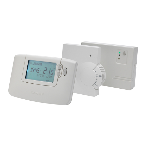
CM900 RF INSTALLATION GUIDE (UK - English)
SIZE AND FOLDING
SIZE WHEN PRINTED
SIZE WHEN FOLDED
MATERIAL
CARTRIDGE
MATT ART
PRINTING
SINGLE SIDE
DOUBLE SIDE
SEE FOLLOWING PAGES FOR COLOUR DESIGNATION. ALL PRINTING MUST BE
CLEAR, FREE OF SMUDGES AND MULTI COLOUR PRINT PROPERLY REGISTERED
SPECIAL INSTRUCTIONS
Folding Sequence
12 page A5 saddle stitched booklet
folded to A6
DO NOT INCLUDE THIS PAGE IN THE PRINTING
ISS
ECO AND DATE
R2
0024168 08/06
A3
A4
x
WEIGHT
70g
ONE COLOUR
x
BLACK
x
DRAWN MKTING
A5
A6
A7
x
x
80g
100g
x
TWOCOLOUR
THREE COLOUR FULL COLOUR
Finished
148m
CM900 RF
Installation Guide
105m
Fron
DATE
MF
BM
08/06
OTHER
BOOKLET
115g
150g
OTHER
xxxxxxxxxx
Part Number
Back
Advertisement
Table of Contents

Subscribe to Our Youtube Channel
Related Manuals for Honeywell Home CM900


Summary of Contents for Honeywell Home CM900
- Page 1 DRAWING DETAILS PART NUMBER ECO AND DATE 42011076-003 0024168 08/06 ARTWORK DESCRIPTION DRAWN MKTING DATE 08/06 CM900 RF INSTALLATION GUIDE (UK - English) SIZE AND FOLDING OTHER BOOKLET SIZE WHEN PRINTED SIZE WHEN FOLDED MATERIAL CARTRIDGE WEIGHT 100g 115g 150g...
-
Page 2: Table Of Contents
2) Installing the CM900 Wireless System ..3 extra large LCD display with backlighting and LoT 2.1 Installing the Receiver Box ........Technology to assist customers during daily use. -
Page 3: Installation Information
Test mode as described in section 2.2.3 Locating the Room Thermostat. If the position is unsuitable the receiver box will not respond and an alternative position must be selected. = Signal Strength Wall Wall Wall Ceiling Max. Signal Length 30 metres Typical example of Building Fabric Signal losses CM900 Wireless - Programmable Room Thermostat... -
Page 4: Installing The Cm900 Wireless System
2) Installing the CM900 Wireless System Please follow the illustrations and information below in sequence to install the receiver box and room thermostat correctly. For applications other than gas boilers, enabling special features and to see what other system options are available refer to section 4) Installer Mode. -
Page 5: Installing The Room Thermostat
NOTE: If the green LED is not switched at specified intervals, the red LED is flashing or if you are installing a replacement receiver box or room thermostat, follow the procedures described in section 5.1 Binding / Rebinding Procedure. CM900 Wireless - Programmable Room Thermostat... -
Page 6: Locating The Room Thermostat
2.2.3 Locating the Room Thermostat While still in the Test Mode, as described in section 2.2.2, the room thermostat should be located taking the following into consideration and reviewing the illustrations below: 1. Find a suitable location where the signal transmission is reliable. Reliable transmission is indicated when the receiver box is flashing the green LED every 6 seconds. -
Page 7: Basic Operation Of The System
Parameters are divided into two groups: - Category 1 parameters – Room Thermostat Setup - Category 2 parameters – System Setup. These are all listed in section 4.5 Installer Parameters Table. CM900 Wireless - Programmable Room Thermostat... -
Page 8: Entering Installer Mode
4.1 Entering Installer Mode COPY DATE PROG AUTO CM927 1..6 The unit will display the first parameter of installer Move the slider switch to the OFF mode. parameter group category 1 (from Parameter n.1 & Press and hold the button and the two to n.19) as shown buttons together. -
Page 9: Using The Room Thermostat For Specific Applications
The normal lower limit of 5°C can be 1) to the desired upper limit. increased up to 21°C to protect inhabitants from cold. Set parameter 7:LL (category 1) to the desired lower limit. CM900 Wireless - Programmable Room Thermostat... -
Page 10: Installer Parameters Table
4.5 Installer Parameters Table 4.5.1 Category 1 - Room Thermostat Settings Parameter Parameter Factory Default Setting Optional Setting Category 1 Parameters – Room Thermostat Settings Display Description Display Description AM-PM / 24hr 1:CL 24 hr clock display 12 hr – AM/PM clock display format Display format Reset Time/ Temp... -
Page 11: Category 2 - System Settings
Relay 20% on / 80% off Communications Instruction The following Parameters are for the control of other Honeywell Home Wireless products such as Wireless Underfloor Heating controls and Wireless Radiator controls. For more information please contact Honeywell Home sales. Room Temperature... -
Page 12: Additional Installation Information
If the red LED still flashes push the button again until binding is successful. 6. Now go to Section 2) Installing the CM900 Wireless System to setup the system. 5.2 Multi-Zone System Multiple room thermostats and receiver box sets can also be used to control multi-zone systems and the CM927/921 room thermostat is compatible with a variety of other Honeywell Home products including HR80 radiator controllers and HCE80 underfloor heating controllers. -
Page 13: Trouble Shooting
5 minutes and the following information can be viewed on the display by pressing the buttons. : model ID, date code (WW/YY) & checksum. Hereby, Honeywell Home declares that this CM927/CM921 room thermostat and HC60NG receiver box are in compliance with the essential requirements and other relevant provisions of Directive 1999/5/EC, 73/23EC and 89/336EC.
Need help?
Do you have a question about the CM900 and is the answer not in the manual?
Questions and answers