Table of Contents
Advertisement
Quick Links
OM‐00745‐01
December 3, 1979
Rev. B 05‐04‐17
INSTALLATION, OPERATION,
AND MAINTENANCE MANUAL
WITH PARTS LIST
80 SERIES PUMP
MODEL
81 1/2B3‐B
THE GORMAN‐RUPP COMPANY D MANSFIELD, OHIO
www.grpumps.com
D
GORMAN‐RUPP OF CANADA LIMITED
ST. THOMAS, ONTARIO, CANADA
Printed in U.S.A.
e
Copyright by the Gorman‐Rupp Company
Advertisement
Table of Contents

Related Manuals for GORMAN-RUPP PUMPS 811/2B3-B


Summary of Contents for GORMAN-RUPP PUMPS 811/2B3-B
- Page 1 OM‐00745‐01 December 3, 1979 Rev. B 05‐04‐17 INSTALLATION, OPERATION, AND MAINTENANCE MANUAL WITH PARTS LIST 80 SERIES PUMP MODEL 81 1/2B3‐B THE GORMAN‐RUPP COMPANY D MANSFIELD, OHIO www.grpumps.com GORMAN‐RUPP OF CANADA LIMITED ST. THOMAS, ONTARIO, CANADA Printed in U.S.A. Copyright by the Gorman‐Rupp Company...
- Page 2 Register your new Gorman‐Rupp pump online at www.grpumps.com Valid serial number and e‐mail address required. RECORD YOUR PUMP MODEL AND SERIAL NUMBER Please record your pump model and serial number in the spaces provided below. Your Gorman‐Rupp distributor needs this information when you require parts or service. Pump Model: Serial Number:...
-
Page 3: Table Of Contents
TABLE OF CONTENTS INTRODUCTION ..........PAGE I - 1 SAFETY ‐... - Page 4 TABLE OF CONTENTS (continued) PUMP MAINTENANCE AND REPAIR ‐ SECTION E ....PAGE E - 1 STANDARD PERFORMANCE CURVE ........PAGE E - 1 PARTS LIST: Pump Model...
-
Page 5: Introduction
80 SERIES OM-00745 INTRODUCTION Thank You for purchasing a Gorman‐Rupp pump. The following are used to alert maintenance per Read this manual carefully to learn how to safely sonnel to procedures which require special atten install and operate your pump. Failure to do so tion, to those which could damage equipment, and could result in personal injury or damage to the to those which could be dangerous to personnel:... -
Page 6: Safety - Section A
80 SERIES OM-00745 SAFETY ‐ SECTION A This information applies to 80 Series ba authorized Gorman‐Rupp distributor sic pumps. Gorman‐Rupp has no con may modify a pump or approve its use trol over or particular knowledge of the for handling volatile, flammable liquids. power source which will be used. - Page 7 OM-00745 80 SERIES low the pump to cool and use extreme to a boil, build pressure, and cause the caution when venting the pump, or pump casing to rupture or explode. when removing covers, plates, plugs, or fittings. Overheated pumps can cause severe burns and injuries.
-
Page 8: Installation - Section B
80 SERIES OM-00745 INSTALLATION - SECTION B Review all SAFETY information in Section A. specific application. Since the pressure supplied to the pump is critical to performance and safety, Since pump installations are seldom identical, this be sure to limit the incoming pressure to 50% of the section offers only general recommendations and maximum permissible operating pressure as practices required to inspect, position, and ar... -
Page 9: Preinstallation Inspection
OM-00745 80 SERIES PREINSTALLATION INSPECTION POSITIONING PUMP The pump assembly was inspected and tested be fore shipment from the factory. Before installation, inspect the pump for damage which may have oc curred during shipment. Check as follows: Use lifting and moving equipment in good repair and with adequate capacity a. -
Page 10: Materials
80 SERIES OM-00745 Materials slopes down to the pump at any point along the suction run, air pockets will be created. Either pipe or hose maybe used for suction and Fittings discharge lines; however, the materials must be compatible with the liquid being pumped. If hose is Suction lines should be the same size as the pump used in suction lines, it must be the rigid‐wall, rein... -
Page 11: Suction Line Positioning
OM-00745 80 SERIES tion inlet because the inflow will carry air down into Suction Line Positioning the sump, and air entering the suction line will re duce pump efficiency. The depth of submergence of the suction line is critical to efficient pump operation. Figure 2 shows If it is necessary to position inflow close to the suc... -
Page 12: Bypass Lines
80 SERIES OM-00745 from excessive shock pressure and reverse rota bolts. The pump casing feet and/or pedestal feet, tion when it is stopped. and the driver mounting bolts should also be tightly secured. If the application involves a high discharge head, gradually close the discharge When checking alignment, disconnect throttling valve before stopping the pump. -
Page 13: V-Belt Drives
OM-00745 80 SERIES MISALIGNED: MISALIGNED: ALIGNED: SHAFTS SHAFTS SHAFTS PARALLEL AND NOT PARALLEL NOT IN LINE SHEAVES IN LINE Figure 3C. Alignment of V‐Belt Driven Pumps Tighten the belts in accordance with the belt manu Figure 3B. Aligning Non‐Spider Type facturer's instructions. -
Page 14: Operation - Section C
OM-00745 80 SERIES OPERATION - SECTION C Review all SAFETY information in Section A. PRIMING Follow the instructions on all tags, labels and Install the pump and piping as described in IN decals attached to the pump. STALLATION. Make sure that the piping connec tions are tight, and that the pump is securely mounted. -
Page 15: Starting
OM-00745 80 SERIES STARTING OPERATION Lines With a Bypass Consult the operations manual furnished with the power source. Close the discharge throttling valve (if so equipped) so that the pump will not have to prime If the pump has been approved for use with petro against the weight of the liquid in the discharge line. -
Page 16: Strainer Check
OM-00745 80 SERIES boil, build pressure, and cause the pump to rup lift, and should then stabilize. If the vacuum reading ture or explode. If overheating occurs, stop the falls off rapidly after stabilization, an air leak exists. pump and allow it to completely cool before servic Before checking for the source of the leak, check the point of installation of the vacuum gauge. - Page 17 OM-00745 80 SERIES curately by placing a contact‐type thermometer rect level (see LUBRICATION in Section E). Bear against the housing. Record this temperature for ing overheating can also be caused by shaft future reference. misalignment and/or excessive vibration. A sudden increase in bearing temperatures is a When pumps are first started, the bearings may warning that the bearings are at the point of failing seem to run at temperatures above normal.
-
Page 18: Troubleshooting - Section D
80 SERIES OM-00745 TROUBLESHOOTING - SECTION D Review all SAFETY information in Section A. Before attempting to open or service the pump: 1. Familiarize yourself with this man ual. 2. Lock out or disconnect the power source to ensure that the pump will remain inoperative. - Page 19 OM-00745 80 SERIES TROUBLE POSSIBLE CAUSE PROBABLE REMEDY Impeller or other wearing parts worn Replace worn or damaged parts. PUMP STOPS OR FAILS TO DELIVER or damaged. Check that impeller is properly RATED FLOW OR centered and rotates freely. PRESSURE (cont.) Impeller clogged.
-
Page 20: Preventive Maintenance
80 SERIES OM-00745 equipped) between regularly scheduled inspec PREVENTIVE MAINTENANCE tions can indicate problems that can be corrected Since pump applications are seldom identical, and before system damage or catastrophic failure oc pump wear is directly affected by such things as curs. -
Page 21: Pump Maintenance And Repair - Section E
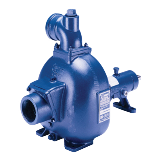
OM-00745 80 SERIES PUMP MAINTENANCE AND REPAIR - SECTION E MAINTENANCE AND REPAIR OF THE WEARING PARTS OF THE PUMP WILL MAINTAIN PEAK OPERATING PERFORMANCE. STANDARD PERFORMANCE FOR PUMP MODEL 81 1/2B3-B Based on 70_ F (21_ C) clear water at sea level Contact the Gorman‐Rupp Company to verify per... - Page 22 80 SERIES OM-00745 SECTION DRAWING PARTS PAGE Figure 1. Pump Model 81 1/2B3-B MAINTENANCE & REPAIR PAGE E - 2...
-
Page 23: Parts List: Pump Model
OM-00745 80 SERIES PARTS LIST Pump Model 81 1/2B3‐B (From S/N 259506 up) If your pump serial number is followed by an “N”, your pump is NOT a standard production model. Contact the Gorman‐Rupp Company to verify part numbers. ITEM PART MAT'L PART NAME... -
Page 24: Pump And Seal Disassembly And Reassembly
80 SERIES OM-00745 PUMP AND SEAL DISASSEMBLY 4. Check the temperature before opening any covers, plates, or AND REASSEMBLY plugs. 5. Close the suction and discharge Review all SAFETY information in Section A. valves. 6. Vent the pump slowly and cau Follow the instructions on all tags, label and de... -
Page 25: Pump Casing And Wear Plate Removal
OM-00745 80 SERIES Pump Casing and Wear Plate Removal spring will be released as the impeller is un screwed. To service the wear plate (22), remove the nuts (19) securing the pump casing to the seal plate (6) and Inspect the impeller and replace it if cracked or pedestal (11). -
Page 26: Shaft And Bearing Removal And Disassembly
80 SERIES OM-00745 Remove the slinger ring (9) from the shaft. Remove the pedestal mounting hardware from the base. Tie and tag any shims used under the mounting feet for leveling. Bearings must be kept free of all dirt and Use snap ring pliers to remove the bearing retain... -
Page 27: Seal Reassembly And Installation
OM-00745 80 SERIES NOTE If a hot oil bath is used to heat the bearings, both the oil and the container must be absolutely clean. If the oil has been previously used, it must be thor When installing the shaft and bearings into oughly filtered. - Page 28 80 SERIES OM-00745 non‐oil based solvent and a clean, lint‐free tissue. If a replacement seal is being used, remove it from Wipe lightly in a concentric pattern to avoid the container and inspect the precision finished scratching the faces. faces to ensure that they are free of any foreign matter.
-
Page 29: Impeller Installation
OM-00745 80 SERIES Slide the shaft sleeve onto the impeller shaft until ket set until the correct clearance is achieved. Se the seal faces contact. Continue to push the sleeve cure the pump casing to the seal plate and pedes through the seal until the sleeve seats squarely tal with the nuts (19). -
Page 30: Power Source
80 SERIES OM-00745 ever comes first. Do not over‐lubricate. Over‐lu Under normal conditions, change the grease after brication will cause the bearings to over‐heat, re each 5000 hours of operation, or at 12 month inter sulting in premature bearing failure. vals, whichever comes first. - Page 31 For Warranty Information, Please Visit www.grpumps.com/warranty or call: U.S.: 419-755-1280 Canada: 519-631-2870 International: +1-419-755-1352 GORMAN‐RUPP PUMPS...
Need help?
Do you have a question about the 811/2B3-B and is the answer not in the manual?
Questions and answers