
Related Manuals for GORMAN-RUPP PUMPS 811/4A3-B


Summary of Contents for GORMAN-RUPP PUMPS 811/4A3-B
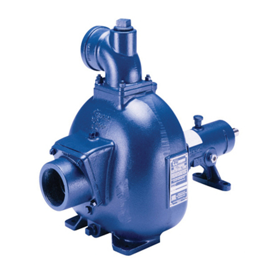
- Page 1 OM‐00780‐03 July 22, 1986 Rev. B 05‐29‐19 INSTALLATION, OPERATION, AND MAINTENANCE MANUAL WITH PARTS LIST 80 SERIES PUMP MODEL 81 1/4A3‐B GORMAN‐RUPP PUMPS www.grpumps.com 1986 Gorman‐Rupp Pumps Printed in U.S.A.
- Page 2 Register your new Gorman‐Rupp pump online at www.grpumps.com Valid serial number and e‐mail address required. RECORD YOUR PUMP MODEL AND SERIAL NUMBER Please record your pump model and serial number in the spaces provided below. Your Gorman‐Rupp distributor needs this information when you require parts or service. Pump Model: Serial Number:...
-
Page 3: Table Of Contents
TABLE OF CONTENTS INTRODUCTION ..........PAGE I - 1 SAFETY ‐... - Page 4 TABLE OF CONTENTS (continued) PUMP MAINTENANCE AND REPAIR ‐ SECTION E ....PAGE E - 1 STANDARD PERFORMANCE CURVE ........PAGE E - 1 PARTS LIST: Pump Model...
-
Page 5: Introduction
80 SERIES OM-00780 INTRODUCTION Thank You for purchasing a Gorman‐Rupp pump. The following are used to alert maintenance per Read this manual carefully to learn how to safely sonnel to procedures which require special atten install and operate your pump. Failure to do so tion, to those which could damage equipment, and could result in personal injury or damage to the to those which could be dangerous to personnel:... -
Page 6: Safety - Section A
80 SERIES OM-00780 SAFETY ‐ SECTION A This information applies to 80 Series ba authorized Gorman‐Rupp distributor sic pumps. Gorman‐Rupp has no con may modify a pump or approve its use trol over or particular knowledge of the for handling volatile, flammable liquids. power source which will be used. - Page 7 OM-00780 80 SERIES low the pump to cool and use extreme closed discharge valve for long periods caution when venting the pump, or of time. If operated against a closed dis when removing covers, plates, plugs, or charge valve, pump components will fittings.
-
Page 8: Installation - Section B
80 SERIES OM-00780 INSTALLATION - SECTION B Review all SAFETY information in Section A. specific application. Since the pressure supplied to the pump is critical to performance and safety, Since pump installations are seldom identical, this be sure to limit the incoming pressure to 50% of the section offers only general recommendations and maximum permissible operating pressure as practices required to inspect, position, and ar... -
Page 9: Positioning Pump
OM-00780 80 SERIES Lifting Pump unit weights will vary depending on the mounting and drive provided. Check the shipping tag on the unit packaging for the actual weight, and Only operate this pump in the direction in use lifting equipment with appropriate capacity. dicated by the arrow on the pump body Drain the pump and remove all customer‐installed and on the accompanying decal. -
Page 10: Connections To Pump
80 SERIES OM-00780 mum use of elbows and fittings, which substan Strainers tially increase friction loss. If elbows are necessary, If a strainer is furnished with the pump, be certain use the long‐radius type to minimize friction loss. to use it; any spherical solids which pass through a strainer furnished with the pump will also pass Connections to Pump through the pump itself. -
Page 11: Suction Line Positioning
OM-00780 80 SERIES tance equal to at least 3 times the diameter of the NOTE suction pipe. The pipe submergence required may be reduced by installing a standard pipe increaser fitting at the Suction Line Positioning end of the suction line. The larger opening size will reduce the inlet velocity. -
Page 12: Alignment
80 SERIES OM-00780 air from the top of the pump during the priming Coupled Drives process. This may be accomplished by installing a When using couplings, the axis of the power bypass line from the top of the pump, back to the source must be aligned to the axis of the pump source of liquid. -
Page 13: V-Belt Drives
OM-00780 80 SERIES straightedge to measure the amount of misalign ment. V‐Belt Drives Do not operate the pump without the When using V‐belt drives, the power source and shields and/or guards in place over the the pump must be parallel. Use a straightedge drive shaft, belts, and/or couplings, or along the sides of the pulleys to ensure that the pul... -
Page 14: Operation - Section C
OM-00780 80 SERIES OPERATION - SECTION C Review all SAFETY information in Section A. PRIMING Follow the instructions on all tags, labels and Install the pump and piping as described in IN decals attached to the pump. STALLATION. Make sure that the piping connec tions are tight, and that the pump is securely mounted. -
Page 15: Starting
OM-00780 80 SERIES STARTING OPERATION Lines With a Bypass Consult the operations manual furnished with the power source. Close the discharge throttling valve (if so equipped) so that the pump will not have to prime If the pump has been approved for use with petro against the weight of the liquid in the discharge line. -
Page 16: Strainer Check
OM-00780 80 SERIES boil, build pressure, and cause the pump to rup lift, and should then stabilize. If the vacuum reading ture or explode. If overheating occurs, stop the falls off rapidly after stabilization, an air leak exists. pump and allow it to completely cool before servic Before checking for the source of the leak, check the point of installation of the vacuum gauge. - Page 17 OM-00780 80 SERIES curately by placing a contact‐type thermometer rect level (see LUBRICATION in Section E). Bear against the housing. Record this temperature for ing overheating can also be caused by shaft future reference. misalignment and/or excessive vibration. A sudden increase in bearing temperatures is a When pumps are first started, the bearings may warning that the bearings are at the point of failing seem to run at temperatures above normal.
-
Page 18: Troubleshooting - Section D
80 SERIES OM-00780 TROUBLESHOOTING - SECTION D Review all SAFETY information in Section A. Before attempting to open or service the pump: 1. Familiarize yourself with this man ual. 2. Lock out or disconnect the power source to ensure that the pump will remain inoperative. - Page 19 OM-00780 80 SERIES TROUBLE POSSIBLE CAUSE PROBABLE REMEDY Impeller or other wearing parts worn Replace worn or damaged parts. PUMP STOPS OR FAILS TO DELIVER or damaged. Check that impeller is properly RATED FLOW OR centered and rotates freely. PRESSURE (cont.) Impeller clogged.
-
Page 20: Preventive Maintenance
80 SERIES OM-00780 equipped) between regularly scheduled inspec PREVENTIVE MAINTENANCE tions can indicate problems that can be corrected Since pump applications are seldom identical, and before system damage or catastrophic failure oc pump wear is directly affected by such things as curs. -
Page 21: Pump Maintenance And Repair - Section E
OM-00780 80 SERIES PUMP MAINTENANCE AND REPAIR - SECTION E MAINTENANCE AND REPAIR OF THE WEARING PARTS OF THE PUMP WILL MAINTAIN PEAK OPERATING PERFORMANCE. STANDARD PERFORMANCE FOR PUMP MODEL 81 1/4A3-B Based on 70_ F (21_ C) clear water at sea level Contact the Gorman‐Rupp Company to verify per... - Page 22 80 SERIES OM-00780 SECTION DRAWING PARTS PAGE Figure 1. Pump Model 81 1/4A3-B PAGE E - 2 MAINTENANCE & REPAIR...
-
Page 23: Parts List: Pump Model
OM-00780 80 SERIES PARTS LIST Pump Model 81 1/4A3‐B (From S/N 859498 Up) If your pump serial number is followed by an “N”, your pump is NOT a standard production model. Contact the Gorman‐Rupp Company to verify part numbers. ITEM PART PART NAME NUMBER... -
Page 24: Pump And Seal Disassembly And Reassembly
OM-00780 80 SERIES PUMP AND SEAL DISASSEMBLY AND REASSEMBLY Before attempting to open or service the Review all SAFETY information in Section A. pump: 1. Familiarize yourself with this man ual. Follow the instructions on all tags, label and de 2. -
Page 25: Pump Casing And Vane Plate Removal
80 SERIES OM-00780 Install the shaft key (17). Install a lathe dog on the moved from the pump before lifting. Lift drive end of the shaft (18) with the “V” notch posi the pump or component only as high as tioned over the shaft key. - Page 26 OM-00780 80 SERIES press the seal stationary seat and element out of the intermediate from the back side. To prevent damage during removal from If no further disassembly is required, see Seal the shaft, it is recommended that bearings Reassembly and Installation. be cleaned and inspected in place.
-
Page 27: Shaft And Bearing Removal And Disassembly
80 SERIES OM-00780 Shaft And Bearing Reassembly And Installation When installing the bearings onto the Clean and inspect the bearings as indicated in shaft, never press or hit against the outer Shaft and Bearing Removal and Disassembly. race, balls, or ball cage. Press only on the inner race. - Page 28 OM-00780 80 SERIES during reassembly. This could result in premature age. Clean and polish the seal area of the shaft. failure. If necessary to reuse an old seal in an emer Small nicks and burrs can be removed using a fine gency, carefully wash all metallic parts in fresh file or emery cloth.
-
Page 29: Impeller Installation
80 SERIES OM-00780 Slide the rotating portion of the seal assembly onto Final Pump Assembly the shaft until the seal faces contact. Be sure the pump and power source are securely Install the seal spring, spring centering washer and mounted to the base. Reconnect the power source seal washer (30). - Page 30 For Warranty Information, Please Visit www.grpumps.com/warranty or call: U.S.: 419-755-1280 Canada: 519-631-2870 International: +1-419-755-1352 GORMAN‐RUPP PUMPS...
Need help?
Do you have a question about the 811/4A3-B and is the answer not in the manual?
Questions and answers