
Related Manuals for GORMAN-RUPP PUMPS 84B3-B


Summary of Contents for GORMAN-RUPP PUMPS 84B3-B
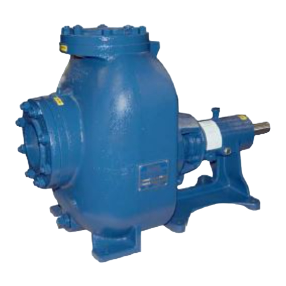
- Page 1 OM‐00939‐03 April 31, 1980 Rev. F 02‐13‐19 INSTALLATION, OPERATION, AND MAINTENANCE MANUAL WITH PARTS LIST 80 SERIES PUMP MODEL 84B3‐B GORMAN‐RUPP PUMPS www.grpumps.com 1980 Gorman‐Rupp Pumps Printed in U.S.A.
- Page 2 Register your new Gorman‐Rupp pump online at www.grpumps.com Valid serial number and e‐mail address required. RECORD YOUR PUMP MODEL AND SERIAL NUMBER Please record your pump model and serial number in the spaces provided below. Your Gorman‐Rupp distributor needs this information when you require parts or service. Pump Model: Serial Number:...
-
Page 3: Table Of Contents
TABLE OF CONTENTS INTRODUCTION ..........PAGE I - 1 SAFETY ‐... - Page 4 TABLE OF CONTENTS (continued) PUMP MAINTENANCE AND REPAIR ‐ SECTION E ....PAGE E - 1 STANDARD PERFORMANCE CURVE ........PAGE E - 1 PARTS LIST: Pump Model...
-
Page 5: Introduction
80 SERIES OM-00939 INTRODUCTION Thank You for purchasing a Gorman‐Rupp pump. The following are used to alert maintenance per Read this manual carefully to learn how to safely sonnel to procedures which require special atten install and operate your pump. Failure to do so tion, to those which could damage equipment, and could result in personal injury or damage to the to those which could be dangerous to personnel:... -
Page 6: Safety - Section A
80 SERIES OM-00939 SAFETY ‐ SECTION A This information applies to 80 Series ba 6. Vent the pump slowly and cau sic pumps. Gorman‐Rupp has no con tiously. trol over or particular knowledge of the 7. Drain the pump. power source which will be used. Refer to the manual accompanying the power source before attempting to begin oper... - Page 7 OM-00939 80 SERIES unit and the National Electric Code or the applicable local code, the National or local code shall take precedence. Do not operate the pump without the shields and/or guards in place over the drive shaft, belts, and/or couplings, or other rotating parts.
-
Page 8: Installation - Section B
See Figure 1 for the approximate physical dimen configuration, and priming must be tailored to the sions of this pump. OUTLINE DRAWING Figure 1. Pump Model 84B3-B PREINSTALLATION INSPECTION b. Check for and tighten loose attaching hard ware. Since gaskets tend to shrink after dry... -
Page 9: Positioning Pump
OM-00939 80 SERIES Lifting Pump unit weights will vary depending on the mounting and drive provided. Check the shipping Only operate this pump in the direction in tag on the unit packaging for the actual weight, and dicated by the arrow on the pump body use lifting equipment with appropriate capacity. -
Page 10: Connections To Pump
80 SERIES OM-00939 tially increase friction loss. If elbows are necessary, Strainers use the long‐radius type to minimize friction loss. If a strainer is furnished with the pump, be certain to use it; any spherical solids which pass through a Connections to Pump strainer furnished with the pump will also pass through the pump itself. -
Page 11: Suction Line Positioning
OM-00939 80 SERIES tance equal to at least 3 times the diameter of the NOTE suction pipe. The pipe submergence required may be reduced by installing a standard pipe increaser fitting at the Suction Line Positioning end of the suction line. The larger opening size will reduce the inlet velocity. -
Page 12: Alignment
80 SERIES OM-00939 air from the top of the pump during the priming must be checked and realigned before operation. process. This may be accomplished by installing a Before checking alignment, tighten the foundation bypass line from the top of the pump, back to the bolts. -
Page 13: V-Belt Drives
OM-00939 80 SERIES MISALIGNED: MISALIGNED: ALIGNED: SHAFTS SHAFTS SHAFTS PARALLEL AND NOT PARALLEL NOT IN LINE SHEAVES IN LINE Figure 3C. Alignment of V‐Belt Driven Pumps Tighten the belts in accordance with the belt manu Figure 3B. Aligning Non‐Spider Type Couplings facturer's instructions. - Page 14 80 SERIES OM-00939 Tension Measurement For example, if the span as measured in Figure 4 is 32 inches (813 mm), the v‐belt cross‐section is C, the smallest sheave diameter is 8 inches, the pump Correct v‐belt tension can be achieved using a v‐ speed is 1250 RPM, and the belts are uncogged belt tension tester and Table 1 or 2.
- Page 15 OM-00939 80 SERIES Table 1. Sheave Diameter (Inches) Table 2. Sheave Diameter (Millimeters) Deflection Force (Lbs.) Deflection Force (KG.) Belt Deflection Force Belt Deflection Force Uncogged Cogged Uncogged Cogged Hy‐T Belts & Torque‐Flex Hy‐T Belts & Torque‐Flex Uncogged & Machined Uncogged &...
-
Page 16: Operation - Section C
OM-00939 80 SERIES OPERATION - SECTION C Review all SAFETY information in Section A. PRIMING Follow the instructions on all tags, labels and Install the pump and piping as described in IN decals attached to the pump. STALLATION. Make sure that the piping connec tions are tight, and that the pump is securely mounted. -
Page 17: Starting
OM-00939 80 SERIES STARTING OPERATION Lines With a Bypass Consult the operations manual furnished with the power source. Close the discharge throttling valve (if so equipped) so that the pump will not have to prime If the pump has been approved for use with petro against the weight of the liquid in the discharge line. -
Page 18: Strainer Check
OM-00939 80 SERIES boil, build pressure, and cause the pump to rup lift, and should then stabilize. If the vacuum reading ture or explode. If overheating occurs, stop the falls off rapidly after stabilization, an air leak exists. pump and allow it to completely cool before servic Before checking for the source of the leak, check the point of installation of the vacuum gauge. - Page 19 OM-00939 80 SERIES curately by placing a contact‐type thermometer rect level (see LUBRICATION in Section E). Bear against the housing. Record this temperature for ing overheating can also be caused by shaft future reference. misalignment and/or excessive vibration. A sudden increase in bearing temperatures is a When pumps are first started, the bearings may warning that the bearings are at the point of failing seem to run at temperatures above normal.
-
Page 20: Troubleshooting - Section D
80 SERIES OM-00939 TROUBLESHOOTING - SECTION D Review all SAFETY information in Section A. Before attempting to open or service the pump: 1. Familiarize yourself with this man ual. 2. Lock out or disconnect the power source to ensure that the pump will remain inoperative. - Page 21 OM-00939 80 SERIES TROUBLE POSSIBLE CAUSE PROBABLE REMEDY Impeller or other wearing parts worn Replace worn or damaged parts. PUMP STOPS OR FAILS TO DELIVER or damaged. Check that impeller is properly RATED FLOW OR centered and rotates freely. PRESSURE (cont.) Impeller clogged.
-
Page 22: Preventive Maintenance
80 SERIES OM-00939 equipped) between regularly scheduled inspec PREVENTIVE MAINTENANCE tions can indicate problems that can be corrected Since pump applications are seldom identical, and before system damage or catastrophic failure oc pump wear is directly affected by such things as curs. - Page 23 PUMP MAINTENANCE AND REPAIR - SECTION E MAINTENANCE AND REPAIR OF THE WEARING PARTS OF THE PUMP WILL MAINTAIN PEAK OPERATING PERFORMANCE. STANDARD PERFORMANCE FOR PUMP MODEL 84B3-B Based on 70_ F (21_ C) clear water at sea level Contact the Gorman‐Rupp Company to verify per...
- Page 24 OM-00939 80 SERIES SECTION DRAWING PARTS PAGE Figure 1. Pump Model 84B3-B PAGE E - 2 MAINTENANCE & REPAIR...
- Page 25 OM-00939 80 SERIES PARTS LIST Pump Model 84B3‐B (From S/N 664926 Up) If your pump serial number is followed by an “N”, your pump is NOT a standard production model. Contact the Gorman‐Rupp Company to verify part numbers. ITEM PART NAME PART ITEM PART NAME...
- Page 26 80 SERIES OM-00939 PUMP AND SEAL DISASSEMBLY AND REASSEMBLY Before attempting to open or service the Review all SAFETY information in Section A. pump: 1. Familiarize yourself with this man Follow the instructions on all tags, label and de ual. cals attached to the pump.
- Page 27 OM-00939 80 SERIES moved from the pump before lifting. Lift Inspect the wear plate for scoring or excessive wear. To remove the wear plate, disengage the the pump or component only as high as hardware (40 and 41). Pull the wear plate out of the necessary and keep personnel away pump casing.
- Page 28 80 SERIES OM-00939 Unscrew the impeller from the shaft. Use caution Use snap ring pliers to remove the bearing retain when removing the impeller; tension on the seal ing ring (22) from the pedestal bore. Remove the spring will be released as the impeller is un bearing shim set (21);...
- Page 29 OM-00939 80 SERIES Clean the bearings thoroughly in fresh cleaning NOTE solvent. Dry the bearings with filtered compressed If a hot oil bath is used to heat the bearings, both the oil and the container must be absolutely clean. If air and coat with light oil.
- Page 30 80 SERIES OM-00939 the bearing bore, push against the outer race. Never hit the balls or ball cage. Position the oil seal (32) in the bearing cap (15) with the lip positioned as shown in Figure 1. Press the Most cleaning solvents are toxic and oil seal into the bearing cap until fully seated.
- Page 31 OM-00939 80 SERIES ROTATING SPRING ELEMENT IMPELLER STATIONARY SEAT IMPELLER ADJUSTING SHIMS IMPELLER SHAFT SHAFT SLEEVE O‐RING SPRING SEAL WASHER PLATE BELLOWS RETAINER Figure 3. Seal Assembly Slide the assembled seal and shaft sleeve onto the shaft until the seal faces contact. Continue to push the sleeve through the seal until the chamfered end seats firmly against the shaft shoulder.
- Page 32 80 SERIES OM-00939 the shaft until tight. Make sure the seal spring seats tight, and that the weight of the lines is indepen squarely over the step on the back of the impeller. dently supported and secure. The clearance between the back of the impeller and the seal plate should be between 0.020 and 0.040 inch (0,51 to 1,02 mm).
- Page 33 OM-00939 80 SERIES Under normal conditions, change the oil each ture condensation. This is especially im 5000 hours or once each year, more frequently if portant in areas where variable hot and the pump is operated continuously or installed in cold temperatures are common.
- Page 34 For Warranty Information, Please Visit www.grpumps.com/warranty or call: U.S.: 419-755-1280 Canada: 519-631-2870 International: +1-419-755-1352 GORMAN‐RUPP PUMPS...
Need help?
Do you have a question about the 84B3-B and is the answer not in the manual?
Questions and answers