Table of Contents
Advertisement
Quick Links
Advertisement
Table of Contents

Subscribe to Our Youtube Channel
Related Manuals for Sercomm NA900B


Summary of Contents for Sercomm NA900B
- Page 1 Home Monitoring Gateway User Guide...
-
Page 2: Table Of Contents
Table of Contents CHAPTER 1 INTRODUCTION ..................... 1 Package Contents ......................1 Specfication ........................1 LEDs ........................... 2 CHAPTER 2 INITIAL INSTALLATION ................5 Requirements........................5 Procedure ........................... 5 CHAPTER 3 BOARD DESCRIPTION .................. 7 Components and connectors .................... 7 Copyright ©... -
Page 3: Chapter 1 Introduction
Chapter 1 Introduction This Chapter provides an overview of the 11N Home Monitoring Gateway's features and capabilities. Congratulations on the purchase of your new 11N Home Monitoring Gateway. The 11N Home Monitoring Gateway is a consumer electronic device, which is used for home monitoring and security. -
Page 4: Leds
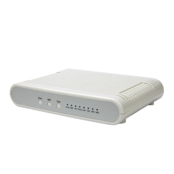
LEDs Front-mounted LEDs The 11N Home Monitoring Gateway has 8 LEDs. Reset This button has two (2) functions: • Reboot. When pressed and released, the 11N Home Monitoring Gateway will reboot (restart). • Clear All Data. This button can also be used to clear ALL data and restore ALL settings to the factory default values. - Page 5 • On (Amber) - Problem occurred while trying to enable the WPS function. • On (Green) - WPS function is enabled. • Flashing - Data is being transmitted or received via the connection. • Service On (Green)- Control Point has made a successful activation to the Portal Server.
- Page 6 Rear Panel Connect the DSL or Cable Modem here. If your modem came with a WAN port cable, use the supplied cable. Otherwise, use a standard LAN cable. (10/100BaseT) LAN (1~4) Port Use standard LAN cables (RJ45 connectors) to connect your PCs to these ports.
-
Page 7: Chapter 2 Initial Installation
Chapter 2 Initial Installation This Chapter covers the software installation of the 11N Home Monitoring Gateway. Requirements • Network cables. Use standard 10/100BaseT network (UTP) cables with RJ45 connectors. Procedure 1. Choose an Installation Site Select a suitable place to install the 11N Home Monitoring Gateway. 2. - Page 8 5. Check the LEDs • The POWER LED should be ON. • The LAN LED should be ON (provided the PC is also ON.)
-
Page 9: Chapter 3 Board Description
Chapter 3 Board Description This Chapter provides board description for the 11N Home Monitoring Gate- way. Components and connectors • 2. USB type A connector • 3. LAN port • 4. WAN port • 5. Expansion slot connectors • 6. Push buttons. •... - Page 10 Console port connection guide For platform debugging, please locate the console cable accompanied with the development kit. Then follow the steps illustrated below: Pin definition 1. Connect cable to console port 2. Execute minicom on Linux host machine...
- Page 11 3. Press Ctrl+A then Z to enter minicom configuration 4. Set Comm port to baud rate 57600, 8 data bits, no parity bits, and one stop bit.
- Page 12 Regulatory Approvals FCC Statement This equipment has been tested and found to comply with the limits for a Class B digital device, pursuant to part 15 of the FCC rules. These limits are designed to provide reasonable protection against harmful interference in a residential installation.
Need help?
Do you have a question about the NA900B and is the answer not in the manual?
Questions and answers