
Related Manuals for Megger TDR2000


Summary of Contents for Megger TDR2000
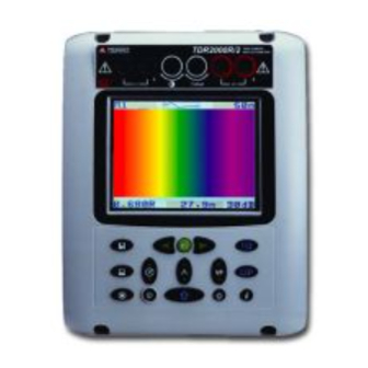
- Page 1 ® Advanced Test Equipment Rentals www.atecorp.com 800-404-ATEC (2832) Time Domain Reflectometer MEGGER CFL 535E - TDR2000 ® User Guide MEGGER ®...
-
Page 2: Table Of Contents
Contents Safety Warnings Introduction Features and Controls Operation Instrument Features Balance Control Velocity Factor Pulse Widths MeterCenter (800) 230-6008 www.MeterCenter.com Memory Features Configuration Menu Techniques to Improve Accuracy Care and Maintenance Specification Symbols used on the instrument are: Repair and Warranty Caution: Refer to accompanying notes. -
Page 3: Safety Warnings
SAFETY WARNINGS This instrument meets the safety requirements of IEC 61010 part 1 to 150V cat III. If it is to be used in situations where hazardous live voltages may be encountered then an additional blocking filter must be used. CAUTION (Risk of electric shock) Although this tester does not generate any hazardous voltages, circuits to which it can be connected could be dangerous due to electric shock hazard or due to arcing (initiated by short circuit). -
Page 4: Introduction
To maximise the instruments range, the identifying a wide range of cable faults. The instrument uses a TDR2000 has an adjustable gain setting on its input that can technique called Time Domain Reflectometry (TDR) which in apply up to 90dB of gain to the reflected signal to allow you to many ways is similar to radar. - Page 5 There are four modes of operation to get “live” results, and these are: The batteries to power the instrument are housed in the compartment on the case back, the cover is held in place with [L1] & [OFF] Trace is acquired from L1 only, internal two screws.
-
Page 6: Features And Controls
Features and Controls usually connected to the faulty line or the line under test. In Xtalk mode, this is the transmitting terminal. 2) Contrast: This is a rotary control that lets the user correct the display contrast for user preference and adjust for the extremes of temperature. - Page 7 7) Range / Configuration: 14) Print / PC: Pressing this button changes the instrument range to the next Pressing this key sends the current screen to an attached lower range. If this button and the shift key are pressed EPSON compatible printer as a screen dump. If pressed with together then the CONFIG menu is invoked.
-
Page 8: Operation
Operation Ensure the test leads are firmly fitted into the sockets of the gain of the instrument can be adjusted. With the gain at the instrument. Ensure the cable(s) under test is (are) de-energised minimum required to see the end of the cable on the trace, if a before connecting the test leads. -
Page 9: Instrument Features
It can be displayed in one of two ways: a ratio of the transmitted pulse The TDR2000 pulse widths range from 20ns to 16µs to speed to the speed of light, or as a distance per microsecond. -
Page 10: Memory Features
CONFIG Options menu. Memory Features The TDR2000 has 15 memory locations, which can be used to store traces from previously tested cables. These may be stored for future analysis or be downloaded to the TRACEMASTER software for analysis on a PC. -
Page 11: Configuration Menu
CONFIGURATION MENU There are two configuration menus - options and setup. The Options menu includes all those settings that will be adjusted in the everyday use of the instrument. The Setup menu includes those settings that are more for the user preferences and calibration and will only be accessed occasionally. - Page 12 From the Config Menu - Setup set the Zero Point to 0. of the cable feature more difficult. To overcome this, the TDR2000 has the ability to Press the MODE key to exit the Config menu and have averaging where the cable is over- display a trace.
-
Page 13: Techniques To Improve Accuracy
Backlight off: This allows the user to set the backlight auto Even in the case when the true end of the cable is still visible, turn off to 1, 2 or 5 minutes. the reflections after the fault may be too obscure to analyse clearly. -
Page 14: Specification
Specification Except where otherwise stated, this specification applies at an Gain: 0 to 90dB in steps of 6dB ambient temperature of 20°C. Velocity Factor: Variable from 0.300 to 0.999 in steps Ranges: 50m, 100m, 200m, 400m, of 0.001 1km, 2km, 4km, 8km, 16km. Repetition rate: Burst of 256 pulses every 1 or 10 seconds. - Page 15 Communications Port: RS-232C compatible Case Dimensions: 250 mm long 1 start bit, 8 data bits, 1 stop bit and 200 mm wide no parity, 9 600 baud standard 110 mm deep Batteries: Instrument weight: 1.5kg (3.3lbs) Eight LR6 (AA) type batteries, manganese-alkali or nickel- cadmium or nickel-metal-hydride cells.
-
Page 16: Repair And Warranty
A number of independent instrument repair companies have repair by suitably trained and qualified personnel. been authorised for repair work on most MEGGER instruments, using genuine MEGGER spare parts. Consult the Appointed The protection is likely to be impaired if for example; it shows Distributor/Agent regarding spare parts, repair facilities, and visible damage;...
Need help?
Do you have a question about the TDR2000 and is the answer not in the manual?
Questions and answers