Advertisement
Quick Links
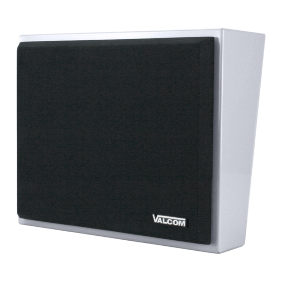
INTRODUCTION
The VIP-410 One-Way IP Wall Speaker enables
voice access to a single zone of one-way paging
over an IP-based LAN/WAN. This allows a page
zone extension anywhere on the network. The
speaker level is electrically adjusted during set up..
The enclosure is made of steel with a durable gray
powder coated finish. The color of the enclosure
can easily be changed to match any decor. A
detachable black clothe grille is included. The
speaker requires an 802.3af PoE compliant network
connection.
Power is provided to the VIP-410 via a Power over
an Ethernet switch meeting the 802.3af
specification. The Valcom VIP-908 Ethernet switch
is ideal for this purpose and will power up to 7 VIP-
800 series devices.
INSTALLATION
FCC Information
This equipment has been tested and found to
comply with the limits for a Class A digital device,
pursuant to Part 15 of the FCC Rules. These limits
are designed to provide reasonable protection
against harmful interference when the equipment is
operated in a commercial environment. This
equipment generates, uses and can radiate radio
frequency energy and if not installed and used in
accordance with the instruction manual, may cause
harmful interference to radio communications.
Operation of this equipment in a residential area
may cause harmful interference in which case the
user will be required to correct the interference at
his own expense.
DIMENSIONS/WEIGHT
•
10.13" H x 12.31" W x 4.63" D
(25.73cm x 31.27cm W x 11.75cm D)
•
Weight: 4.25 LBS (1.91 kg)
Environment
Temperature:
Humidity:
VoIPon www.voipon.co.uk sales@voipon.co.uk Tel: +44 (0)1245 808195 Fax: +44 (0)1245 808299
VIP-410
INSTALLATION INSTRUCTIONS
0 to +40° C
0 to 85% non-precipitating
Precautionary Designations
CAUTION
RISK OF ELECTRIC SHOCK
DO NOT OPEN
CAUTION: To reduce the risk of electric shock,
Do not remove cover.
No user serviceable parts inside.
Refer servicing to qualified serv ice personnel.
This symbol indicates that dangerous
voltage constituting a risk of electric
shock is present within this unit.
This symbol indicates that there are
important operating and maintenance
instructions in the literature accompanying
this unit.
Packing List
Qty.
1
1
1
1
MOUNTING
Remove the screw holding the mounting bracket to
the enclosure. Mount the bracket using appropriate
hardware such as #8 pan head crews. After
making the required connections, reattach the
enclosure to the mounting bracket
Network Connection
The VIP-410 has one CAT-5 RJ-45 network
connector on the rear panel. Use the supplied
CAT-5 patch cable to connect the VIP-410 to
an Ethernet switch. See Fig. 1 for details.
1
Issue 1
Issue 1
Item
VIP-410
VIP-102 Setup CD
VSP Document
RJ-45 Patch Cable
947078
Advertisement

Subscribe to Our Youtube Channel
Related Manuals for Valcom VIP-908


Summary of Contents for Valcom VIP-908
- Page 1 No user serviceable parts inside. an Ethernet switch meeting the 802.3af Refer servicing to qualified serv ice personnel. specification. The Valcom VIP-908 Ethernet switch is ideal for this purpose and will power up to 7 VIP- This symbol indicates that dangerous 800 series devices.
- Page 2 VALCOM LIMITED WARRANTY Valcom, Inc. warrants its products to be free from defects in materials and workmanship under conditions of normal use and service for a period of one year from the date of shipment. The obligation under this warranty shall be limited to the replacement, repair or refund of any such defective device within the warranty period, provided that: inspection by Valcom, Inc.
Need help?
Do you have a question about the VIP-908 and is the answer not in the manual?
Questions and answers