Table of Contents
Advertisement
Quick Links
Warranty
Tenma warrants to the original purchaser this product will be free from defects in
materials and workmanship for a period of one year. In the event that warranty
replacement is required, the unit will be replaced or repaired at the sole discretion of
Tenma Test Equipment. Warranty claims must be processed through the dealer in
which the product was purchased.
This warranty does not include service or parts to repair damage caused by accident,
disaster, misuse, abuse, or improper installation. This warranty is in lieu of all other
expressed warranties. If the product is defective in materials or workmanship as
warranted above, the purchaser's sole remedy shall be repair or replacement as
provided above. In no event will Tenma Test Equipment be liable for any incidental or
consequential damages arising from the use of this product.
Tenma Test Equipment
Distributed Exclusively by MCM Electronics
www.mcmelectronics.com
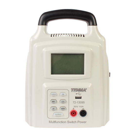
Multipurpose Switch Mode Power Supply
Model 72-13095
User Manual
Keep this manual in a safe place for quick reference at all times. It contains
important safety and operation instructions for correct use. Read through the
manual and pay special attention to the markings and labels of this unit and
equipment to be connected.
Pay special attention to these two types of notices used in this manual.
Advertisement
Table of Contents

Related Manuals for Tenma 72-13095


Summary of Contents for Tenma 72-13095
- Page 1 If the product is defective in materials or workmanship as warranted above, the purchaser’s sole remedy shall be repair or replacement as provided above. In no event will Tenma Test Equipment be liable for any incidental or consequential damages arising from the use of this product.
- Page 2 WARNING: battery. Failure to observe this warning may cause injury to persons and 20. If the charger does not work properly or if it has been damaged, unplug its AC damage to power supply or connected equipment. and DC connection. 21.
- Page 3 7. Voltage Setting Indicator 8. Current Setting Indicator 9. USB Output Display 10. Output ON/OFF Indicator 11. Automatic Fan 12. Power Switch 13. AC Power Input CONTROL MODE SELECTION There are 3 modes, Normal, Charge, and USB mode for the power supply. 1.
- Page 4 large primary display will show output voltage. With no load connected, the Amperage will read zero. Once a load is connected, the Amperage 2.1. Battery Voltage Setting drawn by the load will be displayed on the lower Amp digits. 2.11. Switch on the power supply.
- Page 5 85VAC – 120VAC, 60Hz Input Voltage Input Current 1.6A Voltage range 1~30V Output Rating Current range 0~10A Line Regulation Voltage CV≤1%+3mV ±%of output + offset Load Regulation Voltage CV≤1%+5mV ±%of output + offset Voltage 10mV Measurement Accuracy Current 10mA ≤0.5%+2 word Measured Value Voltage...
Need help?
Do you have a question about the 72-13095 and is the answer not in the manual?
Questions and answers