Advertisement
Quick Links
Edits are in colour, and from an end user who has no affiliation with the supplier or manufac-
turer. No liability is accepted for any information in, or omission from, this document. Your
unit may work differently than described here if it has a different hardware or software ver-
sion.
Use at your own risk
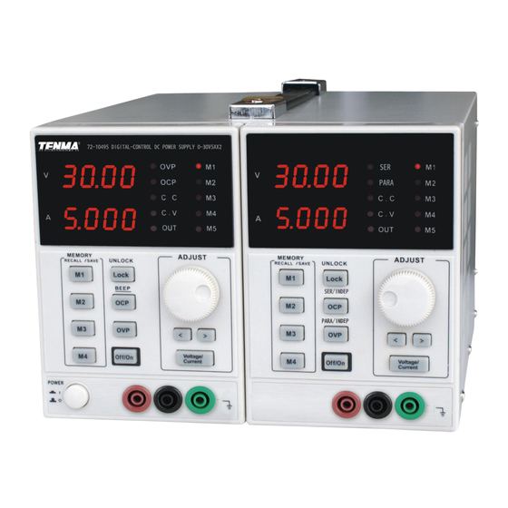
- TENMA 72-10495 (Korad KA3005D-2S): 30V-5A x 2 Channels
- TENMA 72-10500 (Korad KA3003D-2S): 30V-3A x 2 Channels
- TENMA 72-10505 (Korad KA3003D-3S): 30V-3A x 2 Channels & 5V-3A x 1
Velleman supply the single channel version with remote interface as the Velleman LABPS3005D
(which they used to call the PS3005D) The "D" in the Korad model number means no remote in-
terface.
Important notes to avoid damage:
- Do not allow power supply to sink current. (Use diode when charging battery.)
- In series mode, the voltage at the output is the sum of the voltages on the CH1 and CH2
displays
- In parallel mode, the current at the output is the sum of the currents on the CH1 and CH2
displays
- In parallel mode, connect load to CH2 (right hand) channel. (When mains power is turned
on, the power supply defaults to independent mode, and CH1 to whatever voltage and cur-
rent settings are in CH1 memory recall M1, with the load turned off.)
- OCP and OVP do not work in serial and parallel modes.
- For sensitive circuits, disconnect load before:
- Switching load on or off with "OFF/ON" button for that channel
- Switching mains off with the load switched on
Do not leave a load connected to CH2 in SER (serial) mode. If you recall a CH2 memory in
SER mode, only CH2 is updated from that memory and only CH2 turns off. At this time, CH2
output terminals have up to -1.2 V (i.e. reverse polarity) on them, with a short circuit current
of up to -2.8 A.
Important notes to avoid frustration:
- Automatically switches between constant voltage (CV) and constant current (CC) modes
- There is a small +/- voltage and current while the load is switched off (50mV, 100 uA)
- CH2 OUT LED stays on after CH2 OCP/OVP trip disconnects the load.
- CH2 OVP/OCP buttons also control CH1 OVP/OCP
- CH1 OVP/OCP buttons only control CH1 OVP/OCP
- The OCP and OVP LEDs apply to whichever channel last updated them. Pressing either
the OVP or OCP buttons updates both the OVP and OCP LEDs with current state for that
channel.
Advertisement

Related Manuals for Tenma TENMA 72-10495


Summary of Contents for Tenma TENMA 72-10495
- Page 1 - TENMA 72-10495 (Korad KA3005D-2S): 30V-5A x 2 Channels - TENMA 72-10500 (Korad KA3003D-2S): 30V-3A x 2 Channels - TENMA 72-10505 (Korad KA3003D-3S): 30V-3A x 2 Channels & 5V-3A x 1 Velleman supply the single channel version with remote interface as the Velleman LABPS3005D (which they used to call the PS3005D) The "D"...
- Page 4 5 pairs...
- Page 5 CH2 OVP/OCP buttons also control CH1 OVP/OCP voltage CH1 OVP/OCP buttons only control The OCP and OVP LEDs CH1 OVP/OCP are situated on the CH1 display. However they are used for displaying the OCP and OVP state for both channels. They display the state of OCP and OVP for whichever channel the OCP or OVP...
- Page 6 The sound of the beep is sometimes a bit er- ratic. When beep is turned off, some keys may still occasionally beep. When beep is turned on, an OCP or OVP trip will make the unit beep once. If you press and hold the OCP/BEEP button for 2 secs to turn beep on/off, it inadver- tently changes the state of the OCP.
- Page 7 OVP and OCP do not work in series and parallel modes (even though their LEDs might be on) Pressing the SER/ INDEP button for over 2 secs will also inadver- tently change the state of the OCP when exiting SER mode. The current at the out- put is displayed on both CH1 and CH2 displays.
- Page 8 Since the desired constant voltage is also the voltage OVP limit, OVP cannot protect you against inadvertently exceeding the OVP limit using the adjust- ment knob.Since the desired constant current limit is also the OCP limit, OCP Voltage setting: cannot protect you against inadvertently exceeding the OCP limit using the ad- - For use in constant justment knob.
- Page 9 five Cause 1: - The output will refuse to turn on if OVP/OCP is on and the voltage or current present at the output terminals is above the stored set voltage or current values. Cause 2: - OCP was on and the current setting was too small. (Trip is due to power supply in- ternal capacitor in-rush current).
- Page 11 Calibration...
Need help?
Do you have a question about the TENMA 72-10495 and is the answer not in the manual?
Questions and answers