Advertisement
Quick Links
14
To perform the three captures, the movable part of the inspection tip is moved with the trigger. A
capture is made for each position.
Inspection tip (movable part)
Indicates the position to follow to
perform the 3 captures.
Trigger
The icons on screen indicate when you can change the position of the inspection tip and the status
LED as well. When the LED is blue and stops flashing, you can perform a capture.
14a
Using the trigger, slide the movable part of the inspection tip to perform each capture.
Once you are satisfied with the inspection, tap
.
14b
OR
Press the Fiber Inspection Probe capture control button.
15
When the last capture is performed, the analysis starts immediately.
Analyzing Inspection Results
Following the analysis, an image of the identified elements and defects is overlayed on the connector image.
The color of the circles indicates the inspection status of the connector per zone. Red refers to a fail status
whereas green to a pass.
Analyzing Continuity Results
The continuity in a fiber refers to the ability for each fiber of a multifiber patchcord to conduct the light from one
end to the other. With the Fiber Inspection Probe at the receiving end, it is possible to determine on which fibers
discontinuities are found (
).
Analyzing Polarity Results
The polarity of a multifiber patchcord refers to how the fibers are linked between the transmitting (Tx) and
receiving (Rx) connectors. The application refers to the TIA 568 standard which defines three polarity types: A,
B, and C. Any other fiber mappings in a multifiber patchcord will result in an unknown polarity type.
Discontinuity icon
The results are available as an image or in
a detailed table.
A fail status either on the inspection of the
connector, the polarity, or continuity will
result in a global fail status.
The image overlay indicates the inspection
status of the connector per zone.
© 2018 EXFO Inc. All rights reserved.
Printed in Canada (2018-11)
P/N: 1074619
Version: 1.0.0.1
Quick Reference Guide
ConnectorMax MPO Test Solution (iOS)
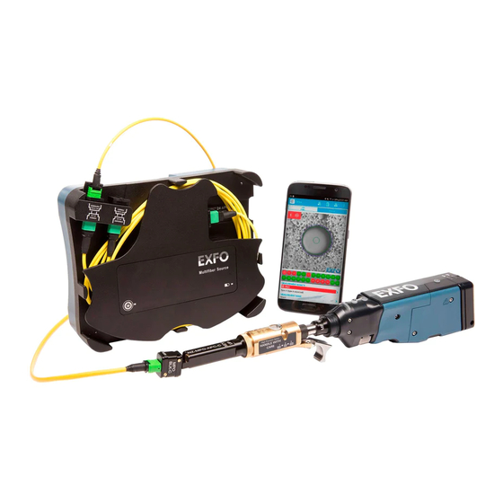
The Multifiber Source (MFS) produces a light pattern that, once injected into a fiber, is detectable by the EXFO's
Fiber Inspection Probe equipped with an MPO tip (12 or 24 fibers). With the MFS, the probe will test the
continuity and polarity of the link under test in addition to performing the connector inspection.
Only the probes identified as MF-Ready allow you to use the MFS or the MPO tip.
Installing the FIP Nozzle
You need to install the removable nozzle and the inspection tip on the probe before you start working. The
nozzle is interchangeable and you can insert it key up or key down. To facilitate the installation process, install
the removable nozzle on the inspection tip first.
1
Install the removable nozzle (key up or key down) on the metal rod of the inspection tip and align the
key of the nozzle with the notch of the inspection tip until you feel it click in place.
Inspection tip
MF-Ready probe
Discontinuities
Tighten the retaining
found on fibers
2
nut clockwise.
are displayed in
To change the nozzle,
red.
untighten,
counterclockwise.
For more information,
refer to the user guide.
MFS-12/MFS-24
Removable nozzle
Retaining nut
Advertisement

Related Manuals for EXFO ConnectorMax MFS-12


Summary of Contents for EXFO ConnectorMax MFS-12
- Page 1 B, and C. Any other fiber mappings in a multifiber patchcord will result in an unknown polarity type. The Multifiber Source (MFS) produces a light pattern that, once injected into a fiber, is detectable by the EXFO’s Fiber Inspection Probe equipped with an MPO tip (12 or 24 fibers). With the MFS, the probe will test the continuity and polarity of the link under test in addition to performing the connector inspection.
- Page 2 Open the dust cap and connect the DUT to the appropriate adapter according to the Tap the Measurement Name row to configure Install the inspection tip on the MF-Ready probe by aligning the key of the probe with the notch of the connections you made in the previous step.
Need help?
Do you have a question about the ConnectorMax MFS-12 and is the answer not in the manual?
Questions and answers