Table of Contents
Advertisement
Available languages
Available languages
Quick Links
UTILITECH and logo design are trademarks or
registered trademarks of LF, LLC. All rights reserved.
ATTACH YOUR RECEIPT HERE
Serial Number
Questions, problems, missing parts? Before returning to your retailer, call our customer
service department at 1-866-994-4148, 8 - 8 p.m., EST, Monday - Sunday. You could also
contact us at partsplus@lowes.com or visit www.lowespartsplus.com.
SM20225
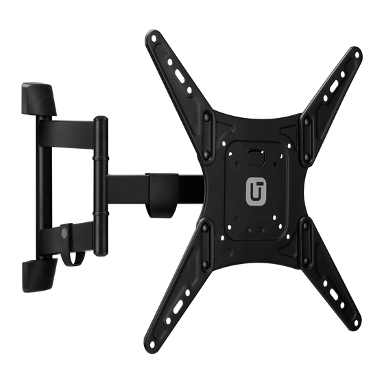
FULL MOTION TV MOUNT
Purchase Date
1
INDOOR/OUTDOOR
MODEL #UT-IO-70C
ITEM #03850903
Español p. 17
Advertisement
Table of Contents

Related Manuals for Utilitech UT-IO-70C


Summary of Contents for Utilitech UT-IO-70C
- Page 1 ITEM #03850903 INDOOR/OUTDOOR FULL MOTION TV MOUNT UTILITECH and logo design are trademarks or MODEL #UT-IO-70C registered trademarks of LF, LLC. All rights reserved. Español p. 17 ATTACH YOUR RECEIPT HERE Serial Number Purchase Date Questions, problems, missing parts? Before returning to your retailer, call our customer service department at 1-866-994-4148, 8 - 8 p.m., EST, Monday - Sunday.
-
Page 2: Package Contents
PACKAGE CONTENTS PART DESCRIPTION QUANTITY PART DESCRIPTION QUANTITY Mounting arm Monitor adapter B End cap Monitor plate (pre-assembled to Monitor adapter A Mounting arm (A)) - Page 3 HARDWARE CONTENTS (shown actual size) M4 x 12 M6 x 15 M8 x 15 Screw Screw Screw Qty. 4 Qty. 4 Qty. 4 M8 x 50 Screw Anchor Qty. 4 Qty. 2 8 mm Lag bolt Qty. 2 M4 x 30 M6 x 30 M8 x 30 Screw...
-
Page 4: Safety Information
SAFETY INFORMATION Please read and understand this entire manual before attempting to assemble, operate or install the product. WARNING • FAILURE TO READ, THOROUGHLY UNDERSTAND, AND FOLLOW ALL INSTRUCTIONS CAN RESULT IN SERIOUS PERSONAL INJURY, DAMAGE TO PERSONAL PROPERTY, OR VOIDING OF FACTORY WARRANTY. -
Page 5: Specifications
SPECIFICATIONS Dimensions and Mounting Configurations 200 mm (7.9 in.) 400 mm (15.7 in.) 100 mm (3.9 in.) 300 mm (11.8 in.) 75 mm (3 in.) 400 mm (15.7 in.) 400 mm (15.7 in.) 300 mm (11.8 in.) - Page 6 ASSEMBLY INSTRUCTIONS 1. Remove two mounting arm screws (PP) from mounting arm (A) and save them for later use. Hardware Used Mounting arm screw 2. Remove monitor plate (E) from mounting arm (A). 3. Determine mounting configuration to use based 7.9 in.
- Page 7 ASSEMBLY INSTRUCTIONS 4. If needed, attach monitor adapters A (C) and monitor adapters B (D) to monitor plate (E) in the desired configuration using carriage screw (OO) and nut (QQ). Secure with included wrench (RR). Hardware Used M6 x 12 Carriage screw M6 nut 5a.
- Page 8 ASSEMBLY INSTRUCTIONS 5b. For curved back flat panel: Attach monitor plate (E) with four spacers (*), four steel washers (KK) and four screws (**). * Note: 5 mm spacers (LL) or 10 mm spacers (MM) can be used depending on your TV. ** Note: Monitor plate (E) can be attached with M4 x 30 screws (EE), M8 x 50 screws (FF), M6 x 30 screws (GG), or M8 x 30 screws (HH) depending on...
- Page 9 ASSEMBLY INSTRUCTIONS 6. If screws are too long, additional 5 mm spacers (LL), 10 mm spacers (MM), and steel washers (NN) may be needed. Hardware Used 5 mm Spacer 10 mm Spacer Steel washer Wood Stud Installation Note: For concrete, proceed to step 12. 7.
- Page 10 ASSEMBLY INSTRUCTIONS 8. Use mounting arm (A) to mark two mounting hole locations. 9. Drill two 7/32 in. pilot holes 2-1/3 in. (60 mm) deep at the marked locations for the mounting holes. 10. Mount top of mounting arm (A) using 8 mm lag bolt (II) with a 1/2 in.
- Page 11 ASSEMBLY INSTRUCTIONS 11. Make sure mounting arm (A) is level, then secure bottom of mounting arm (A) using 8 mm lag bolt (II). Hardware Used 8 mm Lag bolt Concrete Installation 12. Use mounting arm (A) to mark two mounting hole locations.
- Page 12 ASSEMBLY INSTRUCTIONS 14. Insert anchors (JJ) into holes. Tap with hammer (not included) if necessary. Hardware Used Anchor 15. Mount top of mounting arm (A) using 8 mm lag bolt (II) with a 1/2 in. socket wrench (not included). Hardware Used 8 mm Lag bolt 16.
- Page 13 ASSEMBLY INSTRUCTIONS Final Installation 17. Snap end caps (B) onto top and bottom of mounting arm (A). 18. Place mounting plate (E) onto mounting arm (A). 19. Secure mounting plate (E) to mounting arm (A) with the two previously removed mounting arm screws (PP).
- Page 14 ASSEMBLY INSTRUCTIONS Post Installation Level 20. If needed, flat panel can be leveled +/– 3 degrees. ± 3° Note: Leveling will be difficult if mounting arm screws (PP) are too tight. Adjust Tilt 21. To adjust tilt, loosen tilt lever and move panel to desired position.
-
Page 15: Warranty
WARRANTY This product is covered against defects in materials and workmanship for 5 years. The manufacturer will repair or replace the defective component or product, at its sole discretion. Failure to follow product care instructions from the manufacturer will void the warranty. To obtain warranty service, contact customer service at 1-866-994-4148. - Page 17 ARTÍCULO #03850903 SOPORTE PARA TV CON MOVILIDAD UTILITECH y el diseño del logotipo son marcas COMPLETA PARA comerciales o marcas registradas de LF, LLC. Todos los derechos reservados. INTERIOR/EXTERIOR MODELO #UT-IO-70C ADJUNTE SU RECIBO AQUÍ Número de serie Fecha de compra ¿Preguntas, problemas, piezas faltantes? Antes de volver a la tienda, llame a nuestro...
-
Page 18: Contenido Del Paquete
CONTENIDO DEL PAQUETE PIEZA DESCRIPCIÓN CANTIDAD PIEZA DESCRIPCIÓN CANTIDAD Brazo de montaje Adaptador del monitor B Tapa de extremo Placa del monitor (preensamblada en el Adaptador del monitor A brazo de montaje [A]) - Page 19 ADITAMENTOS (se muestran en tamaño real) Tornillo Tornillo Tornillo M4 x 12 M6 x 15 M8 x 15 Cant. 4 Cant. 4 Cant. 4 Tornillo M8 x 50 Ancla de Qty. 4 expansión Cant. 2 Tirafondo de 8 mm Cant. 2 Tornillo Tornillo Tornillo...
-
Page 20: Información De Seguridad
INFORMACIÓN DE SEGURIDAD Lea y comprenda por completo este manual antes de intentar ensamblar, utilizar o instalar el producto. ADVERTENCIA • NO LEER, COMPRENDER COMPLETAMENTE O SEGUIR TODAS LAS INSTRUCCIONES PUEDE PROVOCAR LESIONES PERSONALES GRAVES, DAÑOS A LA PROPIEDAD PERSONAL O LA ANULACIÓN DE LA GARANTÍA DE FÁBRICA. -
Page 21: Especificaciones
ESPECIFICACIONES Dimensiones y configuraciones de montaje 200 mm (7,9 pulg.) 400 mm (15,7 pulg.) 100 mm (3,9 pulg.) 300 mm (11,8 pulg) 75 mm (3 pulg.) 400 mm (15,7 pulg.) 400 mm (15,7 pulg.) 300 mm (11,8 pulg.) -
Page 22: Instrucciones De Ensamblaje
INSTRUCCIONES DE ENSAMBLAJE 1. Retire los dos tornillos (PP) del brazo de montaje (A) y guárdelos para usarlos más tarde. Aditamentos utilizados Tornillo del brazo de montaje 2. Retire la placa del monitor (E) del brazo de montaje (A). 3. Determine la configuración de montaje que 200 mm 400 mm utilizará... - Page 23 INSTRUCCIONES DE ENSAMBLAJE 4. Si es necesario, fije los adaptadores de monitor A (C) y los adaptadores de monitor B (D) a la placa de monitores (E) en la configuración deseada con el tornillo con cabeza de hongo (OO) y la tuerca (QQ).
- Page 24 INSTRUCCIONES DE ENSAMBLAJE 5b. Apto para panel de pantalla plana: fije la placa de monitores (E) con cuatro espaciadores (*), cuatro arandelas de acero (KK) y cuatro tornillos (**). * Nota: se pueden utilizar espaciadores de 5 mm (LL) o de 10 mm (MM) dependiendo del televisor.
- Page 25 INSTRUCCIONES DE ENSAMBLAJE 6. Si los tornillos son muy largos, puede que necesite espaciadores adicionales de 5 mm (LL) y de 10 mm (MM), y arandelas de acero (NN). Televisor Televisor Aditamentos utilizados Espaciador de 5 mm Espaciador de 10 mm Arandela de acero Instalación en viga de madera Nota: para concreto, continúe con el paso 12.
- Page 26 INSTRUCCIONES DE ENSAMBLAJE 8. Utilice el brazo de montaje (A) para marcar las dos ubicaciones de los orificios de montaje. 9. Taladre dos orificios de 7/32 pulg. (5,6 mm) de una profundidad de 2-1/3 pulg. (60 mm) en las ubicaciones que marcó para los orificios de montaje.
- Page 27 INSTRUCCIONES DE ENSAMBLAJE 11. Asegúrese de que el brazo de montaje (A) esté nivelado, luego asegure la parte inferior del brazo de montaje (A) utilizando un tirafondo de 8 mm (II). Aditamentos utilizados Tirafondo de 8 mm Instalación en concreto 12.
- Page 28 INSTRUCCIONES DE ENSAMBLAJE 14. Introduzca las anclas de expansión (JJ) en los orificios. Si es necesario, utilice un martillo (no se incluye). Aditamentos utilizados Ancla de expansión 15. Instale la parte superior del brazo de montaje (A) utilizando un tirafondo de 8 mm (II) con una llave de tuerca de 1/2 pulg.
- Page 29 INSTRUCCIONES DE ENSAMBLAJE Instalación final 17. Presione las tapas de extremo (B) en la parte superior e inferior del brazo de montaje (A). 18. Coloque la placa de montaje (E) en el brazo de montaje (A). 19. Fije la placa de montaje (E) al brazo de montaje (A) con los dos tornillos del brazo de montaje (PP) que retiró...
- Page 30 INSTRUCCIONES DE ENSAMBLAJE Nivel de instalación de los postes 20. Si es necesario, puede nivelar la pantalla plana +/- 3 ± 3° grados. Nota: la nivelación se dificulta si los tornillos del brazo de montaje (PP) están demasiado apretados. Ajuste de la inclinación 21.
- Page 31 GARANTÍA Este producto está cubierto contra defectos en los materiales y la mano de obra por 5 años. El fabricante reparará o reemplazará el producto o componente defectuoso según su criterio. No seguir las instrucciones de cuidado del producto del fabricante anulará esta garantía. Para obtener el servicio de garantía, póngase en contacto con el Servicio al Cliente al 1-866-994-4148.
Need help?
Do you have a question about the UT-IO-70C and is the answer not in the manual?
Questions and answers