Table of Contents
Advertisement
Quick Links
Advertisement
Table of Contents

Related Manuals for Lancom AirLancer MC-54


Summary of Contents for Lancom AirLancer MC-54
- Page 1 AirLancer MC-54 AirLancer PCI-54 AirLancer...
- Page 2 LANCOM Systems shall be liable only to the degree specified in the terms of sale and delivery. The reproduction and distribution of the documentation and software included with this product is subject to written per- mission by LANCOM Systems. We reserve the right to make any alterations that arise as the result of technical develop- ment.
- Page 3 This documentation was created by … … several members of our staff from a variety of departments in order to ensure you the best possible support when using your LANCOM product. In case you encounter any errors, or just want to issue critics or enhance- ments, please do not hesitate to send an email directly to: info@lancom.de...
- Page 4 Information symbols Very important instructions. Failure to observe this may result in damage. Important instruction that should be observed. Additional information that may be helpful but which is not required. Special formatting in body text Bold Menu commands, command buttons, or input fields Inputs and outputs in command-line mode Code <Value>...
-
Page 5: Table Of Contents
2.4.2 Putting the card into your PC ........17 2.4.3 Driver installation for AirLancer MC-54 ......17 3 AirLancer PCI-54 . - Page 6 5.1 Connecting to a company network........31 6 Extension of the LANCOM 3000 Wireless base station ......35 7 Security within the Wireless LAN .
-
Page 7: Introduction
Introduction Introduction The advantages of a radio network (Wireless LAN) are obvious: notebooks and PCs can be set up where they are needed. Due to Wireless LANs, prob- lems with missing connections or structural alterations belong to the past. Network access in conferences or during presentations, access to resources in neighbouring buildings or data exchange with portable terminals are only some possible applications of Wireless LANs. -
Page 8: Central Collecting Point - The Base Station
Introduction 1.2.2 Central collecting point – the base station With an additional base station, a Wireless LAN becomes more comfortable and more efficient. The base station (access point) enables a central admin- istration of the Wireless LAN. Furthermore, with a base station you can also connect an entire cable-bound LAN to a Wireless LAN. -
Page 9: Infrastructure Network
Introduction 1.3.2 Infrastructure network A base station (access point) is needed for connection to an existing network. The base station forms the control center for data exchange within the WLAN. The base station additionally can offer - depending on its product type - access to a cable-based LAN, as well as to the Internet. -
Page 10: Standardized Radio Transmission By Ieee
Introduction An infrastructure-network is excellently suitable as an extension to existing wired LANs. For extension of a LAN in areas, where a wiring is not possible or uneconomical, the infrastructure-network represents an ideal alternative. Standardized radio transmission by IEEE AirLancer client adapters work with the IEEE 802.11 standard. This standard IEEE 802.11 family represents an extension of the already existing IEEE standards for LANs, of which IEEE 802.3 for Ethernet is the most popular one. - Page 11 Introduction the distance and/or on the quality of the connection. With increasing dis- tance and diminishing connecting quality the transmission rate lowers to 5,5 Mbps, afterwards to 2 and finally to 1 Mbps. The range of the transmission distances is between up to 150 m in open expanses and in buildings typically up to 30 m.
-
Page 12: The Airlancer 54 Models
Introduction have an effect on the range. Decisive is frequently an optimal placement of the radio stations (both network adapters and base stations). The AirLancer 54 models The AirLancer series with 54 Mbps data transfer rate features several mod- els. You have the possibilty to extend standard PCs and a multitude of mobile computers for access to the Wireless LAN: AirLancer MC-54ag •... -
Page 13: The Next Chapters
In the following two chapters you will find detailed descriptions and installa- tion instructions for the AirLancer variants. Each AirLancer type has got its own chapter. You may advance straight forward to your model’s chapter. AirLancer MC-54: chapter 2 on page 15. • AirLancer PCI-54: chapter 3 on page 19. - Page 14 Introduction AirLancer...
-
Page 15: Airlancer Mc-54
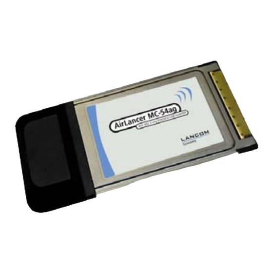
AirLancer MC-54 AirLancer MC-54 In this chapter you will find a description of the AirLancer MC-54 and a step-by-step instruction for starting the card. After installation of hardware, drivers and the AirLancer software, you have to set up the access to a Wire- less LAN. -
Page 16: Installation
Flickering – card is in power save mode • 3 Integrated antenna Installation The installation of AirLancer MC-54 takes place in four steps: a Check the system preconditions b Put the AirLancer MC-54 into your PC c Driver installation d Setting up for accessing the Wireless LAN – you will find the instruction for this configuration step in chapter 4 ’The AirLancer Client Manager’... -
Page 17: Putting The Card Into Your Pc
2.4.3 Driver installation for AirLancer MC-54 In the course of the plug&play hardware identification of Windows ME, Win- dows 98 SE, Windows XP and Windows 2000, you will see that your compu- ter identifies the new hardware automatically, just a short time after insertion of the card. - Page 18 AirLancer MC-54 AirLancer...
-
Page 19: Airlancer Pci-54
AirLancer PCI-54 AirLancer PCI-54 In this chapter you will find a description of the radio network card AirLancer PCI-54 and a step-by-step instruction for starting it. This chapter will end with the successful installation of hardware and drivers. The following configura- tion of the access to a Wireless LAN is described in chapter 5. -
Page 20: Installation
AirLancer PCI-54 1 AirLancer PCI-54 2 External antenna (The kind of the external antenna may vary from the illustation above.) 3 Connection for external antenna 4 Plug-in socket for PCI bus Installation The installation of AirLancer PCI-54 takes place in five steps: a Checking the system preconditions b Hardware installation of the AirLancer PCI-54 c Connection of the external antenna... -
Page 21: Installing Airlancer Pci-54
AirLancer PCI-54 PC with at least one free PCI slot (PCI specification 2.1 or better), at least • 300 MHz processor, at least 32 MByte of RAM. CD ROM disk drive • One of the following operating systems: • Windows 98 SE (Second Edition) •... -
Page 22: Driver Installation For Airlancer Pci-54
AirLancer PCI-54 e Insert carefully the AirLancer PCI-54 into the free slot. Make sure that the card has got a clean seat and screw up the assembly sheet on the casing. Put on the PC casing and screw it up. g Screw up the external antenna onto the antenna connection of the Air- Lancer PCI-54. -
Page 23: The Airlancer Client Manager
The AirLancer Client Manager The AirLancer Client Manager The AirLancer AirLancer Client Manager is the main program for configura- tion and management of AirLancer radio adapters. It is available for the fol- lowing operating systems: Windows 98 SE (Second Edition) •... -
Page 24: Starting The Airlancer Airlancer Client Manager
If the AirLancer Client Manager should not appear in the task bar, you can start it manually out of the menu Programs / LANCOM / AirLancer-54 Cli- ent Tools. The AirLancer Client Manager will appear on the task bar then. - Page 25 The AirLancer Client Manager a Change in AirLancer Client Manager to the index card Profile Manage- ment. Here you can adjust the standard profile for AirLancer or add a new profile. b Select the command New to add a new configuration profile. Assign a name to the new profile under Profile Name and specify one or more wanted network names (SSID).
- Page 26 The AirLancer Client Manager a base station (access point), or whether you want to establish ad-hoc-connections (peer-to-peer-group). Ad-hoc networks are only possible in the 2,4 GHz frequency band using IEEE 802.11g and IEEE 802.11b. Ad-hoc networks are not available with IEEE 802.11a in the 5 GHz band.
-
Page 27: Overview Of The Functions
The AirLancer Client Manager e Complete the profile configuration with OK and activate the new profile by clicking on the profile and then Activate. Check your country settings in the menu Action under Country Select . Please notice that for a legal operation of your AirLancer radio card a cor- rect country setting is mandatory, since the regulations for operating a radio network may differ in different countries. -
Page 28: Encryption Settings
The AirLancer Client Manager as well as the currently selected frequency band, the signal strength, the name of the selected profile and your own IP address. Information about sent and received data can be found under Diagnostics, under the Advanced tab there are statistics and further information about transfered frames and potential transmission errors shown. -
Page 29: Sliding Key Change
The AirLancer Client Manager When entering hexadecimal values, the number of required characters for a key will double. For a WEP64 key, 10 hexadecimal numbers have to be entered, 26 for WEP128, and 32 characters for WEP152. With alpha-numeric input (ASCII), the WEP keys consist accordingly of 5, 13 or 16 characters. Numerous Wireless LAN devices of other manufacturers only accept hexade- cimal values as WEP keys or may generate even special characters from arbi- trary passwords. - Page 30 The AirLancer Client Manager AirLancer...
-
Page 31: Configuration Example
Since they are out of the office most time anyway, their new workplaces are not wired anymore. Instead, a Wireless LAN access point enables to access the corporate Intranet services (e.g. LANCOM 3550 Wireless). Since the sales representatives with their notebooks must have access to the network also in other departments of the company, further base stations will be installed. - Page 32 Configuration example LAN. LANCOM 3550 Wireless serve as Wireless LAN base stations and ena- ble a fast LAN connectivity at up to 54 Mbps. Mobile station leaves changes to floor A and … floor B. Connection via LAN To be able to join the WLAN base station and exchange data with the LAN, the WLAN cards of the notebooks as well as the base stations must have the matching settings in different parameters.
- Page 33 SPX protocols are additionally needed in Novell networks only. Information regarding configuration of base stations can be found in the doc- umentation of your LANCOM Wireless base station and in the electronical documentation of your CD. After installing the radio network cards, all functions and services are availa-...
- Page 34 Configuration example AirLancer...
-
Page 35: Extension Of The Lancom 3000 Wireless Base Station
Due to a second, from outside accessible cardbus slot, it is possible to upgrade base stations of the LANCOM 3000 Wireless series with a second radio card of the LANCOM AirLancer series, and to extend it this way with a second radio cell, for example with new radio standards. - Page 36 Extension of the LANCOM 3000 Wireless base station the it. Remove now carefully the blind slide-in module of the external cardbus slot. Slip-in now the AirLancer MC-54 card into the cardbus slot and restart your device by plugging the power supply cable in again.
-
Page 37: Security Within The Wireless Lan
MAC address (Media Access Control), which is world-wide unique per device. The MAC address is programmed into the hardware and cannot be changed. Wireless LAN devices by LANCOM Systems have got a MAC address label on the casing. AirLancer... -
Page 38: Encryption Of The Data Transfer (Wep)
The access to an infrastructure network can be restricted to known MAC addresses for certain Wireless LAN devices solely. To do so, Access Control lists are available within the LANCOM base stations, in which the granted MAC addresses can be deposited. -
Page 39: Tipps For Handling Keys
Security within the Wireless LAN WEP encryption requires calculating time in the Wireless LAN devices and can slightly impair the data transfer rate. 7.3.2 Tipps for handling keys The security of encryption procedures can be substantially increased the by paying attention to some important rules for handling keys. Keep keys as secret as possible. -
Page 40: 802.1X / Eap
IPSec-based VPN. Required components are the LANCOM VPN option and the LANCOM VPN Client software for Windows 2000 and XP. For other ope- rating systems client software from other manufacturers is available. -
Page 41: Appendix
Appendix Appendix Technical data AirLancer MC-54ag / MC-54g AirLancer PCI-54ag interface PC Card (Cardbus) PCI (Spec. 2.1) WLAN connection 54 Mbps, IEEE 802.11g 54 Mbps, IEEE 802.11g 11 Mbps, IEEE 802.11b 11 Mbps, IEEE 802.11b 54 Mbps, IEEE 802.11a (only MC- 54 Mbps, IEEE 802.11a 54ag) Antenna connection... -
Page 42: Radio Channels
Appendix Radio channels 8.2.1 Radio channels in the 2,4 GHz frequency band In the frequency range from 2400 to 2483 MHz are up to 13 channels availa- ble, from which maximally 3 are non-overlapping. The following overview shows which channels are supported by the different regions (EU/WORLD). Frequency range 2400–2500 MHz Channel-No. -
Page 43: Radio Channels In The 5 Ghz Frequency Band
Appendix 8.2.2 Radio channels in the 5 GHz frequency band In the frequency range from 5,13 to 5,805 GHz up to 19 non-overlapping chan- nels are available in Europe. The following overview shows which channels are allowed in different regions. Channel-No. -
Page 44: Restrictions Of Use Within Eu
Appendix Restrictions of use within EU In European countries the 5 GHz frequency band is divided into three sub- bands, to which different use conditions can apply. The three sub-bands are defined as follows: Lower frequency range from 5,15 to 5,25 GHz •... - Page 45 Appendix Country Restrictions Greece The use in the 5 GHz frequency band is actually forbidden! The use in the 2,4 GHz frequency band is permitted in closed environments, but forbidden in free areas. Iceland When using TPC and DFS all three frequency ranges may be used in the 5 GHz band.
-
Page 46: Declaration Of Conformity
Appendix Declaration of conformity 8.4.1 European Union (CE) The CE declarations of conformity for AirLancer MC-54 and AirLancer PCI-54 are available for download on the LANCOM Systems web site (www.lan- com.de). AirLancer... - Page 47 Appendix AirLancer...
Need help?
Do you have a question about the AirLancer MC-54 and is the answer not in the manual?
Questions and answers