
Related Manuals for Ecler CA40


Summary of Contents for Ecler CA40
- Page 1 CA40 COMPACT AMPLIFIER AV Integration Micro-amplifier USER MANUAL 50-0243-0105 CA40 EN...
-
Page 2: Table Of Contents
INDEX IMPORTANT REMARK......................3 IMPORTANT SAFETY INSTRUCTIONS ................3 IMPORTANT NOTE ........................5 COMPLIANCE WITH INTERNATIONAL STANDARDS ........... 5 INTRODUCTION ........................6 5.1. Main characteristics ........................6 INSTALLATION.......................... 7 6.1. Location and assembly ......................7 6.2. Mains connection ........................7 6.3. -
Page 3: Important Remark
IMPORTANT REMARK The lightning flash with arrowhead symbol, within an equilateral triangle, is intended to alert the user to the presence of uninsulated “dangerous voltage” within the product’s enclosure that may be of sufficient magnitude to constitute a risk of electric shock to persons. The exclamation point within an equilateral triangle is intended to alert the user to the presence of important operating and maintenance (servicing) instructions in the literature accompanying the appliance. - Page 4 9. Do not defeat the safety purpose of the polarized or grounding type plug. A polarized plug has two blades with one wider than the other. A grounding type plug has two blades and a third grounding prong. The wide blade or the third prong are provided for your safety.
-
Page 5: Important Note
Technical Services. Ecler CA40 comes with a 3-year warranty. COMPLIANCE WITH INTERNATIONAL STANDARDS The CA40 micro amplifier complies with the following international standards: • EN55103-1 Electromagnetic Compatibility. Product family standard for audio, video, audio-visual and... -
Page 6: Introduction
INTRODUCTION The CA40 is a very small stereo amplifier with numerous remotely controlled functions (RS-232 serial port, infrared receiver, 0-10 VDC remote control port), and is ideal for integrating audiovisual applications with other devices: educational classes, meeting rooms and multimedia presentations, business premises, etc. -
Page 7: Installation
6.1. Location and assembly The CA40 is suitable for installation on a wall or under a surface (table, shelf, cupboard, etc.), thanks to its design and layout of its connectors, controls and LED indicator lights. 6.2. Mains connection The amplifier is powered by alternating current through its external power source: 100- 240 VAC and 50-60 Hz. -
Page 8: Audio Input Connections
Turntables CANNOT BE CONNECTED directly to this device because none of the inputs have an RIAA preamp. The CA40 has the following operating modes according to the input sources selected as active: • LINE 1: only LINE 1 input is sent to the mix bus to be amplified and delivered to the L and R OUT outputs •... -
Page 9: Audio Output Connections
Remember that the minimum work impedance for the amplifiers in mono or stereo mode is 4, and when working in bridge mode it is 8. For correct operation of the CA40, under no circumstances must you work with impedances lower than those specified above. - Page 10 Pin 2 (RxD) Pin 3 (TxD) Pin 5 (Signal Gnd) • Receiver IR: the built-in IR receiver gives general volume control of the CA40 and its MUTE ON / OFF function from the REVO-IR remote control included with the unit.
-
Page 11: Operation And Usage
The system defaults to volume adjustment mode. In this mode, the VOL/MUTE knob on the front panel acts on the general output volume of the CA40. This controller has a maximum of 64 steps between the unit's minimum and maximum volume. When turned, it will adjust the volume while the LED LEVEL light is flashing. - Page 12 The full procedure for accessing and operating in these special modes and the options available in each are set out in the following graph: Notes: 1. If the device is in special mode for 10 seconds and the front knob is not touched, the equipment automatically reverts to VOL/MUTE mode.
-
Page 13: Auto Standby Function
7.3. AUTO STANDBY Function The AUTO STANDBY function (idle or low consumption mode) means you can install the CA40 in inaccessible places and leave the device connected to the mains power supply indefinitely because when no signal is detected, it automatically goes into standby mode, saving energy. -
Page 14: Led Indicators
7.4. LED indicators • SP: The signal presence or SP LED indicator shows that there is a signal in the amplifier input. This lights up when the input level reaches the established detection threshold. • CLIP: The saturation or CLlP LED indicator comes on when the signal delivered to the speakers is close to the amplifier's clipping or saturation level. -
Page 15: Micro Switches On The Rear Panel
(LINE 1 or 2) when the activation threshold set is reached. • AUTO STANDBY: Switch the AUTO STANDBY function on (ON) or off. When the function is on, the CA40 will automatically go into STANDBY or low consumption mode in the absence of audio signals in its inputs. -
Page 16: Lock Mode
7.6. Lock mode To switch the CA40 lock mode on or off hold in the VOL/MUTE control for 10 seconds from the VOL/MUTE mode. The LED SETTING indicators will flash 3 times to indicate that lock mode is now on. When in lock mode the device cannot be managed using the VOL/MUTE control (it will flash three times to show that it is in that mode when you turn the knob). -
Page 17: Diagrams And List Of Functions
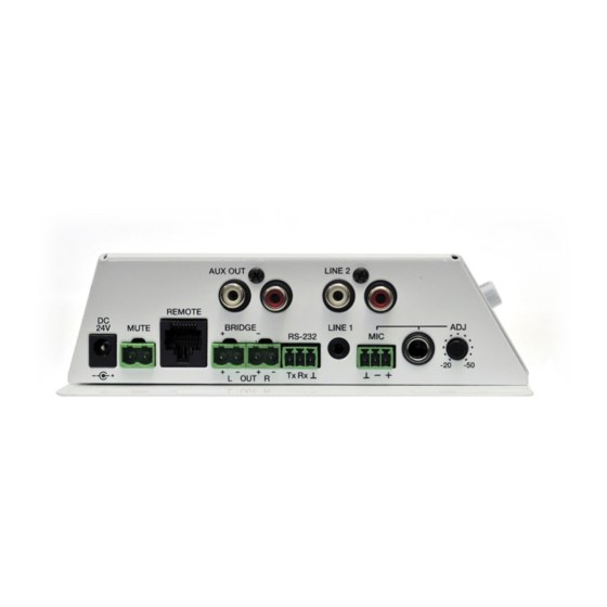
DIAGRAMS and LIST OF FUNCTIONS LEVEL indicator light 17 BRIDGE / STEREO micro switch BASS indicator light 18 MONO / STEREO micro switch TREBLE indicator light 19 DC24V power connector LIN 1 indicator light 20 MUTE remote control LIN 2 indicator light 21 RJ-45, REMOTE connector MIC indicator light 22 OUT L amplified output... -
Page 18: Block Diagram
BLOCK DIAGRAM CONFIGURATION DIAGRAM JUMPERS FACTORY ADJUST Phantom Sensitivity -6dB Phantom Sensitivity -6dB... -
Page 19: Características Técnicas
CARACTERÍSTICAS TÉCNICAS CA40 Power STEREO 2x18W@4Ω 1% THD 2x22W@4Ω 10% THD 2x10W@8Ω 1% THD 2x12W@8Ω 10% THD MONO BRIDGE 1x36W@8Ω 1% THD 1x44W@8Ω 10% THD Frequency response 20Hz - 50kHz (-3dB) THD+Noise @ 1kHz Full Pwr. SPKR OUT < 0.15% THD+Noise AUX OUT <... - Page 20 NEEC AUDIO BARCELONA S.L. reserves the right to make changes or improvements in the design or manufacturing that may affect these product specifications. For technical queries contact your supplier, distributor or complete the contact form on our website, Support / Technical requests. Motors, 166‐168 08038 Barcelona ‐ Spain ‐ (+34) 932238403 | information@ecler.com www.ecler.com...