
Subscribe to Our Youtube Channel
Related Manuals for Curtiss-Wright DuraCOR 80-40

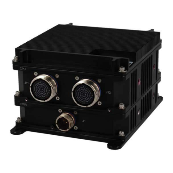
Summary of Contents for Curtiss-Wright DuraCOR 80-40
- Page 1 USER MANUAL DuraCOR 80-40 Rugged Modular Core i7 Mission Computer with PCI Express Expansion and Dual GigE DUCOR-80-40-XX MNL-0642-01 Rev A5 ECO-5370 Effective: 19 Jan 18...
- Page 2 DuraCOR 80-40 User Manual Disclaimer Although the information contained herein has been carefully verified, Parvus Corporation assumes no responsibility for errors that might appear in this document or for damage to property or persons resulting from improper use of this manual or related software.
-
Page 3: Table Of Contents
Parvus Power Supply ........................... 14 CPU Block Diagram ..........................15 Chapter 2 Operating Description ................... 16 Connecting to the DuraCOR 80-40 ......................16 Device Connection ..........................16 System Connectors ..........................17 Starter Cableset for Base Unit ......................18 ... - Page 4 DuraCOR 80-40 User Manual Chapter 4 Specifications ......................40 Mechanical Specifications ........................... 40 Weight ..............................40 Construction ............................40 Dimensions ............................40 Base Unit Dimensions ........................40 Base Unit With One Expansion Segment (EXP) Dimensions ............45 ...
- Page 5 DuraCOR 80-40 User Manual List of Figures Figure 1. Mission Computer (DUCOR-80-40-00)..................8 Figure 2. Mission Computer with Expansion Segments (DUCOR-80-40-10/20) ......... 8 Figure 3. Functional Diagram ........................10 Figure 4. Base System Interconnect Block Diagram ................. 12 ...
-
Page 6: Chapter 1 Introduction
I/O. Chapter 2 explains how to operate the DuraCOR 80-40. It describes the system connectors and cables, and includes procedures for starting the system, using the hot-swappable SSD drives, installing and using cards in the expansion segments, adding zeroization capabilities, and modifying BIOS settings. -
Page 7: Description Of Safety Symbols
Chapter 1 Introduction DuraCOR 80-40 User Manual Description of Safety Symbols The following safety symbols are used in this manual and indicate potentially dangerous situations. Warning! Danger, electrical shock hazard! Personal injury or death could occur. Also damage to the system, connected peripheral devices, or software could occur if the warnings are not followed carefully. -
Page 8: Overview
Cisco IOS-managed DuraMAR 5915 router and/or application I/O into a single appliance combination of computer + router + switch + application I/O. The DuraCOR 80-40 is completely sealed (IP67), requires no active cooling, includes a military-grade power supply supporting aircraft (MIL-STD-704F) and ground vehicle (MIL-STD-1275D) voltages, and features a hinged panel on the rear with two slots for removable 2.5”... -
Page 9: Features
Chapter 1 Introduction DuraCOR 80-40 User Manual Features High Performance CPU Intel 2nd Generation Core i7 (Sandy Bridge) Processor, 2.2 GHz , Dual-Core, 4-8 GB DRAM with Integrated GPU and Advanced Vector Extensions (AVX) Signal Processing Connectivity and I/O ... -
Page 10: Functional Description
The DuraCOR 80-40 is a rugged expandable mission computer based on a Dual-Core 2nd Generation Core i7 (Sandy Bridge), 2.2 GHz processor. The power supply used on the DuraCOR 80-40 has been designed to satisfy the expandability and customization needs of the system. The integration of power-demanding modules such as GPUs, frame grabbers, and high performance switches and/or router is possible because of more than 100W of power head-room. -
Page 11: Configurations
Product Product Number Breakout Description Cableset Mission Computer DuraCOR 80-40-00 CBL-80-40-00 DuraCOR 80-40, 2.2GHz, Corei7-2655LE, 8GB RAM Mission Computer with 1 CBL-80-40-00, DuraCOR 80-40, 2.2GHz, Corei7-2655LE, 8GB RAM, DuraCOR 80-40-10 Expansion Segment DTK-80-40-0X* 1x Expansion Segment Mission Computer with 2... -
Page 12: Base System Interconnect Block Diagram
The DuraCOR 80-40 is built with modular interlocking chassis segments to support multiple configurations. The DuraCOR 80-40 base system consists of the CPU module and the power supply module. Each module contains a PCB that provides an internal power/control bus that interconnects the modules, provides Ethernet and zeroization signals, and supplies power. -
Page 13: Expansion Segments
Chapter 1 Introduction DuraCOR 80-40 User Manual Expansion Segments In expansion segment configurations, additional modules are added between the CPU and power supply. Figure 5 shows a base system with two expansion segments. Depending on the configuration ordered, the expansion segments may be pre-populated with a variety of I/O boards, or empty (for customer installation of boards). -
Page 14: Parvus Power Supply
Chapter 1 Introduction DuraCOR 80-40 User Manual Parvus Power Supply The bottom board is a Parvus power supply. The rugged, isolated power supply is capable of supplying power output over extended temperature ranges (-40 to +71C per MIL-STD-810G). Featuring a rugged mechanical design, this power supply is designed to operate without any active cooling and provide resistance to high levels of shock and vibration. -
Page 15: Cpu Block Diagram
Chapter 1 Introduction DuraCOR 80-40 User Manual CPU Block Diagram Figure 7. CPU Block Diagram MNL-0642-01 Rev A5 ECO-5370 Effective: 19 Jan 18 Page 15 of 59... -
Page 16: Chapter 2 Operating Description
Moreover, EMI gaskets are Al-Ag-filled fluorosilicone to seal the system against EMI. Connecting to the DuraCOR 80-40 Device Connection Figure 8 shows several examples of typical connections that can be made with the DuraCOR 80-40 mission computer. Figure 8. Example Device Connections... -
Page 17: System Connectors
DuraCOR 80-40 User Manual System Connectors Figure 9 shows the connectors on the front panel of a DuraCOR 80-40 with two expansion segments. In all configurations, the CPU connectors are on top and the power connector is on the bottom. -
Page 18: Starter Cableset For Base Unit
DuraCOR 80-40 User Manual Starter Cableset for Base Unit You should test the DuraCOR 80-40 and cabling or interfaces prior to installation in the target system to ensure full operational capability. Full bench-top testing can be performed by using the Parvus starter cableset available for this unit or by using a custom set of cables made specifically for the intended target system, vehicle, or craft. -
Page 19: Installing Cards In The Expansion Segments
Chapter 2 Operating Description DuraCOR 80-40 User Manual Installing Cards in the Expansion Segments To access an expansion segment for board removal or installation, you must remove the modules above the expansion segment. Removing Modules The modules attach to each other by 8-32 screws at the four corners of each module. -
Page 20: Removing A Board
Chapter 2 Operating Description DuraCOR 80-40 User Manual Removing a Board This section provides the general procedure for removing a board from an EXP. 7. Disconnect any cables from the IO board to the board.. 8. Remove any spacers and bus extenders from the board. -
Page 21: Installing Custom Boards
These instructions assume that you have already built a custom cable to connect the board to J13 or J14 on the front panel of the EXP (see the pinout descriptions in "J13 Standard Expansion Segment" or "J14 Standard Expansion Segment"). Ideally all boards installed in the DuraCOR 80-40 will be connected through either the PCIe or PCI bus. -
Page 22: Figure 15. Board Stack In An Exp
Chapter 2 Operating Description DuraCOR 80-40 User Manual As Figure 15 illustrates, an EXP can hold three low-profile cards, two below the brackets and one above. The board-to-board distance is .6", .662" pitch. BOARD BOARD BOARD BOARD BOARD BUS EXTENDER... -
Page 23: Basic Operating Procedures
Chapter 2 Operating Description DuraCOR 80-40 User Manual 14. Connect the board to J13 or J14 using your custom cable. 15. Connect the modules together. Basic Operating Procedures This section describes basic operating procedures, including the power-on sequence, running the BIOS configuration program, using SSDs, and zeroizing the system. -
Page 24: Running The Bios Setup Utility
Chapter 2 Operating Description DuraCOR 80-40 User Manual Running the BIOS Setup Utility This section describes the BIOS settings required for the following DuraCOR 80-40 features: Hot-swappable SATA drives HDMI audio GPIO Hot-Swappable SATA Drives 21. On the Advanced tab, select SATA Configuration in BIOS. -
Page 25: Using Ssds
Chapter 2 Operating Description DuraCOR 80-40 User Manual Using SSDs The SSD bay on the back of the CPU module has two slots for removable 2.5" SATA solid state disks (SSDs). The figure shows the bay with one SSD inserted and one SSD partially inserted. -
Page 26: Ssd Mounting Tray
Chapter 2 Operating Description DuraCOR 80-40 User Manual SSD Mounting Tray Parvus offers factory-mounted SSDs, or you can purchase an empty mounting tray and install your own SSD. Factory-Mounted SSDs The following pre-mounted SSDs are available from Parvus. Item Number... -
Page 27: Mounting An Ssd In The Mounting Tray
Chapter 2 Operating Description DuraCOR 80-40 User Manual Mounting an SSD in the Mounting Tray Parvus offers an empty mounting tray (MCH-80-40-00) for 2.5" form factor SSDs. 25. To mount an SSD in the tray, use the M3x4x0.5 flathead screws provided. -
Page 28: Zeroization
Chapter 2 Operating Description DuraCOR 80-40 User Manual Zeroization For data security, zeroization capabilities can easily be added to the DuraCOR 80-40 system. The zeroization signal can be sent to the hard drives, operating system, and other sections of the DuraCOR 80-40. -
Page 29: Chapter 3 Connector Descriptions
Chapter 3 Connector Descriptions DuraCOR 80-40 User Manual Chapter 3 Connector Descriptions This chapter identifies the pinouts and signal descriptions for the DuraCOR 80-40. It also provides connector part numbers along with suggested mating connector details. Connector Specifications Receptacle Used For... -
Page 30: J11 Cpu-A Connector Pinouts
Chapter 3 Connector Descriptions DuraCOR 80-40 User Manual J11 CPU-A Connector Pinouts J11 provides the signals for the CPU-A connectors in the base unit. P/N: D38999/20FG35BN (Shell Size 21) Figure 19. Connector J11 CPU-A Page 30 of 59 MNL-0642-01 Rev A5... - Page 31 Chapter 3 Connector Descriptions DuraCOR 80-40 User Manual J11 Pin Number Signal Name J11 Pin Number Signal Name VGA RED Analog Red Ground VGA GREEN Analog Green Ground VGA BLUE Analog Blue TMDS_D2# DVI data 2 - Ground TMDS_D2 DVI data 2 +...
-
Page 32: J12 Cpu-B Connector Pinouts
Chapter 3 Connector Descriptions DuraCOR 80-40 User Manual J12 CPU-B Connector Pinouts P/N: D38999/20FG35BA (Shell Size 21) Figure 20. Connector J12 CPU-B USB Grounds should be switched to Chassis pins to meet EMI/EMC Isolation in a vehicle that is well grounded for USB devices that tie system GND to the cable shield. - Page 33 Chapter 3 Connector Descriptions DuraCOR 80-40 User Manual J12 Pin Number Signal Name J12 Pin Number Signal Name Ground GPIO17 GP input/output 17 USB2# minus channel USB2 GPIO16 GP input/output 16 USB2 plus channel USB2 Ground USB2VCC 5 volt for USB2...
-
Page 34: Gpio Connector Pinouts
Chapter 3 Connector Descriptions DuraCOR 80-40 User Manual GPIO Connector Pinouts The table contains the GPIO (2X10 0.100” Pitch) IDC connector pinout on the standard cable set for the DuraCOR 80-40. GPIO Pin Number Signal Name GPIO 00 GPIO 01... -
Page 35: J13 Standard Expansion Segment
J13 can be referenced to GND or Chassis by adding/removing zero ohm resistors on R1-1, R1-2, and R1-3 on both sides of PCB-1456-01. Consult Curtiss-Wright Salt Lake City Application Engineering if you have questions. P/N: D38999/20FF35BA (Shell Size 19) Figure 21. - Page 36 Chapter 3 Connector Descriptions DuraCOR 80-40 User Manual J13 Pinout 40-Pin Con Pairs 38999 J1 40-Pin Con Pairs 38999 J1 J11 - 1 1 Pos J12 - 1 18 Pos J11 - 2 2 Pos J12 - 2 19 Pos...
-
Page 37: J14 Standard Expansion Segment
J14 can be referenced to GND or Chassis by adding/removing zero ohm resistors on R2-1, R2-2, and R2-3 on both sides of PCB-1456-01. Consult Curtiss-Wright Salt Lake City Application Engineering if you have questions. P/N: D38999/20FF35BB (Shell Size 19) Figure 22. - Page 38 Chapter 3 Connector Descriptions DuraCOR 80-40 User Manual J14 Pinout 40-Pin Con Pairs 38999 J1 40-Pin Con Pairs 38999 J1 J21 - 1 1 Pos J22 - 1 18 Pos J21 - 2 2 Pos J22 - 2 19 Pos...
- Page 39 Chapter 3 Connector Descriptions DuraCOR 80-40 User Manual Connector Designator J6 (MFR FCI, PN: 98424-G52-08LF) is the connector with two available USB Ports. The pinout is as follows: Signal USB8 P USB8 N USB8VCC USB7 P USB 7 N USB7VCC...
-
Page 40: Chapter 4 Specifications
Cooling: Natural Passive Convection/Conduction. No Moving Parts Dimensions The table summarizes the physical dimensions of the DuraCOR 80-40, excluding connectors and mounts. Each expansion segment adds 2" (5.08 cm) to the system height. The drawings following the table illustrate the dimensions in different views. -
Page 41: Figure 24. Base Unit Front View
Chapter 4 Specifications DuraCOR 80-40 User Manual 4-40 THREADED INSERTS, .155” Figure 24. Base Unit Front View MNL-0642-01 Rev A5 ECO-5370 Effective: 19 Jan 18 Page 41 of 59... -
Page 42: Figure 25. Base Unit Side View
Chapter 4 Specifications DuraCOR 80-40 User Manual 4X 5/16-18 THREADED INSERTS .400” Figure 25. Base Unit Side View Page 42 of 59 MNL-0642-01 Rev A5 ECO-5370 19 Jan 18... -
Page 43: Figure 26. Base Unit Rear View
Chapter 4 Specifications DuraCOR 80-40 User Manual CHASSIS GND 1X 1/4-20 THREADED INSERT, .375” Figure 26. Base Unit Rear View MNL-0642-01 Rev A5 ECO-5370 Effective: 19 Jan 18 Page 43 of 59... -
Page 44: Figure 27. Base Unit Top View
Chapter 4 Specifications DuraCOR 80-40 User Manual Figure 27. Base Unit Top View Page 44 of 59 MNL-0642-01 Rev A5 ECO-5370 19 Jan 18... -
Page 45: Base Unit With One Expansion Segment (Exp) Dimensions
Chapter 4 Specifications DuraCOR 80-40 User Manual Base Unit With One Expansion Segment (EXP) Dimensions Each standard expansion segment adds 2.0” (5.08 cm) to the overall height. For the top view and mounting dimensions, refer to Figure 27. Figure 28. Base Unit with One EXP Angle View Figure 29. -
Page 46: Figure 30. Base Unit With One Exp Rear View
Chapter 4 Specifications DuraCOR 80-40 User Manual CHASSIS GND 1X 1/4-20 THREADED INSERT, .375” Figure 30. Base Unit with One EXP Rear View Page 46 of 59 MNL-0642-01 Rev A5 ECO-5370 19 Jan 18... -
Page 47: Base Unit With Two Expansion Segments (Exp) Dimensions
Chapter 4 Specifications DuraCOR 80-40 User Manual Base Unit With Two Expansion Segments (EXP) Dimensions Each standard expansion segment adds 2.0” (5.08 cm) to the overall height. For the top view and mounting dimensions, refer to Figure 27. Figure 31. Base Unit with Two EXPs Angle View Figure 32. -
Page 48: Figure 33. Base Unit With Two Exps Rear View
Chapter 4 Specifications DuraCOR 80-40 User Manual CHASSIS GND 1X 1/4-20 THREADED INSERT, .375” Figure 33. Base Unit with Two EXPs Rear View Page 48 of 59 MNL-0642-01 Rev A5 ECO-5370 19 Jan 18... -
Page 49: Mounting Instructions
The DuraCOR 80-40 can be mounted vertically or horizontally. Vertical Mounting Vertical mounting holes have the same pattern for all three configurations. Curtiss-Wright recommends using ¼” - 20 UNC bolts of appropriate grade depending on the application. Figure 34. Vertical Mounting Holes Horizontal Mounting The pattern for horizontal mounting holes depends on the configuration. -
Page 50: Figure 36. Horizontal Mounting Holes Base Unit With 1 Exp
Chapter 4 Specifications DuraCOR 80-40 User Manual Figure 36. Horizontal Mounting Holes Base Unit with 1 EXP Figure 37. Horizontal Mounting Holes Base Unit with 2 EXPs Page 50 of 59 MNL-0642-01 Rev A5 ECO-5370 19 Jan 18... -
Page 51: Technical Specifications
Chapter 4 Specifications DuraCOR 80-40 User Manual Technical Specifications High Performance Processor Intel Core i7-2655LE (Sandy Bridge), Dual Core, Quad Thread Support, 4MB L3 Cache, 64-Bit Instruction Set, Intel BD82QM67 Platform Controller Hub, Intel HD Graphics 3000, 256-bit Advanced Vector Extensions (AVX) ... -
Page 52: Network
Chapter 4 Specifications DuraCOR 80-40 User Manual Network 2x Gigabit Ethernet LAN Interfaces (10/100/1000Mbps) Serial 2x EIA RS232 Serial Ports, 250 Kbps Max 6x USB 2.0 Ports Video Analog Video Output (up to 2048x1536 pixels) ... - Page 53 Chapter 4 Specifications DuraCOR 80-40 User Manual Figure 38. Maximum current available on 3.3V rail Figure 39. Maximum current available on 5V rail Figure 40. Maximum current available on 12V rail MNL-0642-01 Rev A5 ECO-5370 Effective: 19 Jan 18 Page 53 of 59...
-
Page 54: Environmental Specifications
Chapter 4 Specifications DuraCOR 80-40 User Manual Environmental Specifications Qualified to MIL-STD-810G/DO-160G: Temperature Operating Temperature: -40ºC to +71ºC (-40ºF to +160ºF) Clockspeed 100% @ up to 65ºC Clockspeed throttled to 80% @ 71ºC Storage Temperature: -55ºC to +85ºC (-67ºF to +185ºF) Shock/Vibration ... -
Page 55: Reliability
Chapter 4 Specifications DuraCOR 80-40 User Manual Reliability No Moving Parts; Passive Cooling; Conformal Coated Boards for Humidity and Tin Whisker Mitigation MTBF: See Qualification Test Report. Software Specifications Available operating systems: Pre-installed Linux or Special Ordered with Windows 7 or Windows Embedded / Real-Time Operating System ... -
Page 56: Chapter 5 Troubleshooting
DuraCOR 80-40 User Manual Chapter 5 Troubleshooting Product Identification The product is labeled with the Curtiss-Wright P/N and serial number. Please refer to this information when communicating with Curtiss-Wright, Salt Lake City. Technical Assistance If you have a technical question or if you cannot isolate a problem with your product, please call or e-mail... -
Page 57: Chapter 6 Contact Info
Chapter 6 Contact Info DuraCOR 80-40 User Manual Chapter 6 Contact Info Company contact info: Curtiss-Wright 3222 S. Washington St. Salt Lake City, Utah, USA 84115 (801) 483-1533 FAX (801) 483-1523 Website: http://www.curtisswrightds.com/parvus Sales: +1(800) 483-3152 or (801) 483-1533 slp_sales@curtisswright.com... -
Page 58: Appendix A Power Supply
Appendix A Power Supply DuraCOR 80-40 User Manual Appendix A Power Supply 12-36 VDC Input PCA-1411-01 Figure 41. Horizontal Mounting Holes Base Unit with 2 EXPs Page 58 of 59 MNL-0642-01 Rev A5 ECO-5370 19 Jan 18... - Page 59 Appendix A Power Supply DuraCOR 80-40 User Manual MNL-0642-01 Rev A5 ECO-5370 Effective: 19 Jan 18 Page 59 of 59...
Need help?
Do you have a question about the DuraCOR 80-40 and is the answer not in the manual?
Questions and answers