
Subscribe to Our Youtube Channel
Related Manuals for Hardlife Utility 204016DP


Summary of Contents for Hardlife Utility 204016DP
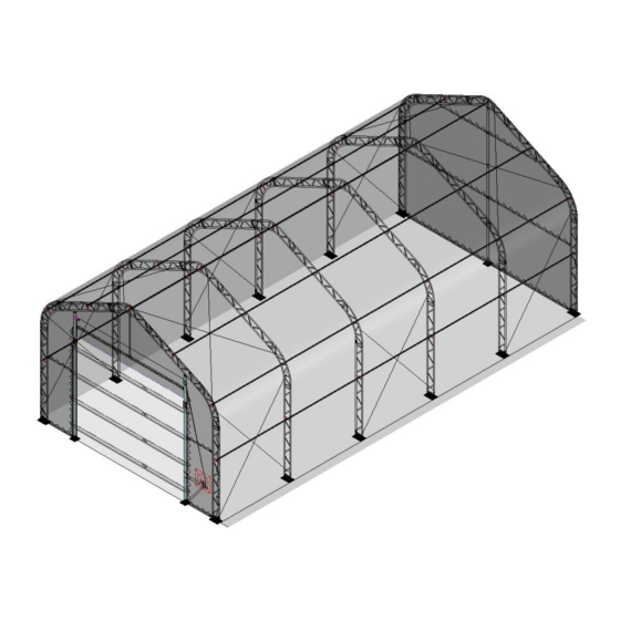
- Page 1 Fabric Building Model# 204016DP 20’x40’x16’ W6.1x L12.2 x H4.88m Assembly Instructions Page 1...
-
Page 2: Recommended Tools
RECOMMENDED TOOLS Equipment List Speed Wrench 22#.23#.24# Hammer (30lb) Rope (12#) Long Tape (50m) Hammer Drill*1 Lifter*2 Crane*1 Forklift*1 Protective equipment Page 2... - Page 3 YOU MUST READ THIS DOCUMENT BEFORE YOU BEGIN TO ASSEMBLE THE SHELTER. Thank you for purchasing our shelter. When properly assembled and maintained, this product will provide years of reliable service. These instructions include helpful hints and important information needed to safely assemble and properly maintain the shelter. Please read these instructions before you begin.
- Page 4 Fabric Building 20'x40'x16' (W6.1xL12.2xH4.88m) Parts List Part Qty/ Description Code top truss for 2nd to 5th arch top truss for 1st arch (front wall) top truss for 6th arch (back wall) roof truss for 2th to 5th arch roof truss for 1st arch (front wall) roof truss for 6th arch (back wall) shoulder truss for 1st to 6th arch upright truss for 2nd to 5th arch...
- Page 5 bolt M8x50 for truss swaged end connection bolt M10x70 for purlin connection end plug (Φ32) for tensioning tube No.9 belt for ratchet on base plate knitting rope for roof cover (2 1 pack bundles) roof cover duct tape expansion bolt steel wire turnbuckle steel wire clamp steel wire...
- Page 6 base plate for back door cross beam for front door vertical tube for door beam No.30 side rail for front wall (two sides) upper rail for back wall middle rail for back wall lower rail for back wall rail for installing winch support tube for rail No.35 pole for door opening front door bracing tube (2pcs/set)
- Page 7 cable tie for fixing front and back cover expansion bolt steel wire for front door bundle steel wire clamp for front door winch for front door front and back cover 1 each Page 7...
-
Page 8: Installation Process
INSTALLATION PROCESS A—BASE PLATES INSTALLATION Please refer to the below diagram to mark the position of base plates The measurement is from center to center of base plates. Referring to the diagram and confirm the place of base plates. ENSURE THAT THE FOUNDATION IS SQUARE. Note: The expansion bolt (No.18, 49) applies for fixing base plate on concrete ground. - Page 9 B—FRAME INSTALLATION First Arch and Front Wall 1. Find Trusses (No.1A, 2A, 3, 4A) for first arch and connect them by bolt M8x50 (No.11). 2. Find relative parts of posts and rails for front wall and assemble them according to the below diagram.
- Page 10 Second Arch to Fifth Arch Installation 3. Find Trusses (No.1, 2, 3 and 4) for second to fifth arch and connect them by bolt M8x50 (No.11). Page 10...
- Page 11 Sixth Arch and Back Wall Installation 4. Find Trusses (No.1B, 2B, 3 and 4A) for sixth arch and connect them by bolt M8x50 (No.11). 5. Find relative parts of posts and rails for back wall and assemble them according to the below diagram.
- Page 12 Purlin and Steel Wire Installation 6. Lift the assembled arches onto base plates (No.7 and 8) and connect them by bolt M8x50 (No.11). 7. When finish installing the first and second arches, install purlin (No.5) and connect them by bolt M10x70 (No.12).
- Page 13 C-INSTALLING COVER Roof Cover Installation NOTE: DO NOT install the cover onto the frame of your building in high wind conditions. A slight breeze is the most advantageous for cover installation. To take advantage of the breeze, pull the cover up over the arches with the breeze blowing in the cover like a sail filled with air. 1.
- Page 14 Front Cover and Mechanical Door Installation 1. Install the mechanical door refer to the diagram bellow. 2. Install front cover (No.53) to the first arch and posts and rails on front wall by rope (No.47) and cable tie (No.48). Mechanical Door Installation Page 14...
- Page 15 Front Cover Installation Page 15...
-
Page 16: Back Cover Installation
Back Cover Installation 3. Install back cover (No.53) to the sixth arch and posts and rails on back wall by rope (No.47) and cable tie (No.48). Now your assembly is completed Page 16...
Need help?
Do you have a question about the 204016DP and is the answer not in the manual?
Questions and answers
what does it cost to install