
Subscribe to Our Youtube Channel
Related Manuals for Hardlife Utility C2020


Summary of Contents for Hardlife Utility C2020
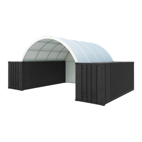
- Page 1 INSTRUCTION MANUAL C2020 / C2040 FRONT PANEL WITH WINCH DOOR CLOSED BACK PANEL www.hardlifeutility.com...
-
Page 3: Table Of Contents
TABLE OF CONTENTS COMPONENT LIST ..................TOOLS REQUIRED FOR INSTALLATION ............ SITE PREPARATION ..................FRONT / BACK PANEL SPECIFICATIONS ........... FRONT WALL ASSEMBLY ................FRONT COVER INSTALLATION ..............BACK WALL ASSEMBLY ................BACK COVER INSTALLATION ..............MAINTENANCE ..................... www.hardlifeutility.com... -
Page 4: Component List
COMPONENT LIST COMPONENT C2020 / C2040 DESCRIPTION CODE (Quantity) Both End Panels’ Base Plate at the Side Base Plate for Front Door Both End Panels’ Base Plate at the Middle Standing Legs at the Side Standing Legs at the Front Panel’s Side Winch Door’s Left Lower Track... - Page 5 Cover for the Front Panel Cover for the Back Panel Ropes 1 Bundle M10 x 90 mm Bolts M8 x 70 mm Carriage Bolts M10 x 30 mm Bolts Dropping Tubes for the Winch Door 1 Group 450 mm Stake Pegs 700 mm Stake Pegs Door Side Splint Clips...
-
Page 6: Tools Required For Installation
2. Lay out all the components within the marked-out site, in the approximate locations at which they will be assembled. This makes preliminary work easier on an open, clear space rather than having parts scattered in the way. FRONT / BACK PANEL SPECIFICATIONS DIMENSIONS C2020/C2040 End Panels Overall Dimensions (m) 6W X 5.6H www.hardlifeutility.com... -
Page 7: Front Wall Assembly
FRONT WALL ASSEMBLY Figure 1 1. Install both end panels’ base plates at the side (component code 8) and the base plates for the front door (component code 8A), as shown in Figure 1. 2. Secure the base plates at the side (8) using two 450 mm stake pegs (component code 34) each, and secure the base plates for the front door (8A) using two 700 mm stake pegs (component code 35) each, as shown in Figure 2. - Page 8 Figure 2 6. Secure the lower and upper tracks using M10 x 90 mm bolts (component code 29) and the door side splint (component code 36), as shown in Figure 2. Secure the upper tracks (11L and 11R) to the arch us- ing M10 x 30 mm bolts (component codes 32), as shown in Figure 2.
-
Page 9: Front Cover Installation
Figure 3 10. Connect the winch door’s suspending tube (component code 12A) to the winch door beam using M10 x 90 mm bolts (component code 29), as shown in Figures 1 and 2. Secure the winch door’s suspending tube to the arch using M10 x 30 mm bolts (component code 32), as shown in Figure 2. NOTE: If an angle iron is available in the installation kit, weld the angle iron to the top bent tube of the arch and use clips and matching bolts to connect the winch door’s suspending tube to the arch. - Page 10 Figure 4 shown in Figure 4. 2. Pull one end of the steel wire on the winch wheel (component code 12C) through the double pulley to the single pulley, wrapping the wire around the door beam. Pull the other end of the steel wire directly to the double pulley, as shown in Figure 4.
-
Page 11: Back Wall Assembly
BACK WALL ASSEMBLY 1. Install both end panels’ base plate at the side (component code 8) and both end panels’ base plate at the middle (component code 8B), as shown in Figure 5. Secure the 8 and 8B base plates using two 450 mm stake pegs (component code 34) each, as shown in Figure 5. -
Page 12: Back Cover Installation
Figure 6 5. Insert the upper standing legs at the middle of the back panel (component code 16) into component code 15, and secure using M8 x 70 mm carriage bolts (component code 30), as shown in Figure 5. The upper standing legs are connected to the arch using clips (component code 37), as shown in Figure 5. -
Page 13: Maintenance
Figure 7 MAINTENANCE • Adjust the front and back covers every month to ensure you always have flat and tensioned covers. • Inspect the shelter regularly, and replace damaged components. www.hardlifeutility.com... - Page 14 Hardlife Advantage ECONOMICAL SHELTERS The best price guarantee in the UK. 24-HOUR DISPATCH Dispatch of orders within 24 hours of receiving your payment (subject to availability). 5-YEAR SPARE PART REPLACEMENT Spare part availability for 5 years from the date of purchase. EFFICIENT AFTER SALES SUPPORT Lifelong technical assistance for all our products.
- Page 15 www.hardlifeutility.com...
- Page 16 Unit 4, Dawson Road, Bletchley, Milton Keynes, MK1 1LH United Kingdom Call us: +(44) 01525 30 90 70 / 01525 85 19 12...
Need help?
Do you have a question about the C2020 and is the answer not in the manual?
Questions and answers