
Related Manuals for KickAss CONTROL HUB


Summary of Contents for KickAss CONTROL HUB
- Page 1 CO N T R O L H U B USER MANUAL VER 0.15...
-
Page 2: Table Of Contents
- - - - - - - - - - - - - - - - - - - - - - - - - - - - - - - - - - - - - - - - - - - - - - - - - - - - - - - - - - - Mounting Items On The Control Hub... -
Page 3: Introduction
Ÿ Ensure suitable gauge wiring is used. Ÿ Do not allow any loose metal objects to fall inside the control hub or enter the ports. Ÿ It is the customers responsibility to ensure the unit is adequately mounted. Ÿ... -
Page 4: Overview
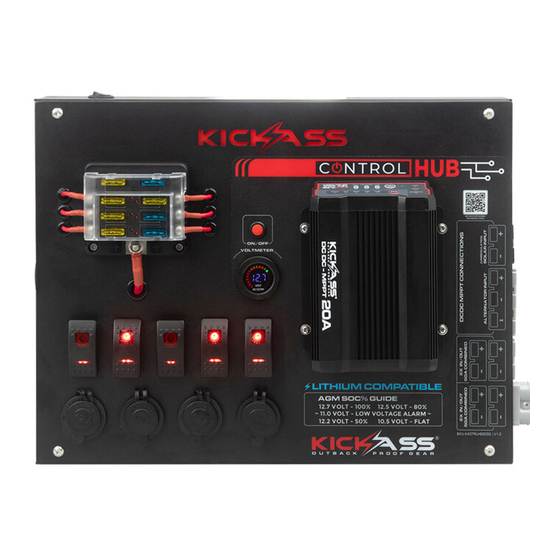
OVERVIEW WHATS INCLUDED 1 X CONTROL HUB (WITH OPTIONAL DCDC CHARGER) 3MM HEX KEY MIDI FUSE MINI BLADE FUSE STD BLADE FUSE BLUE BLADE TERMINALS YELLOW BLADE TERMINALS BLUE BLADE TERMINALS YELLOW RING TERMINALS... - Page 5 SWITCH LABELS FUSE BOX LABELS...
-
Page 6: Features
FEATURES Volt meter with low battery alarm Volt Meter Optional Switch 20A DCDC Charger FRONT VIEW with Solar Input 6 way pre-wired fuse block with two spares 5x Back lit Rocker switches Bottom Entry Cable Gland 1x 10A Cig Socket Quick Charge QC3.0 USB + Type C PD Port (45W max) 2x 2.4A USB... -
Page 7: Wiring Diagram
40A Midi Fuse Post for DCDC Charger DCDC Output Charger Wiring Precut Holes for 50A Midi Fuse for KickAss Lithium Remote 2x Anderson Style Display Unit In/Out Plugs 50A Midi Fuse Main Positive for 2x Anderson Terminal Post Style In/Out Plugs... -
Page 8: Wiring Without Dcdc Charger
Optional DCDC Charger optional DCDC Charger DCDC Charger Negative Connection Post Anderson mounting Output 50A Midi Fuse for Precut Holes for KickAss Lithium Remote 2x Anderson Style Display Unit In/Out Plugs 50A Midi Fuse Main Positive for 2x Anderson Style Terminal Post... -
Page 9: Connections & Accessories
Note: The battery voltage table on the sticker of the control hub is to be used as a guide for SOC % only, check your battery specifications for accuracy. -
Page 10: Outputs
OUTPUTS USBs Ÿ 2x 2.4A High Powered USB (White) Ÿ 1x Quick Charge QC 3.0 Ultra high powered usb output (5V/3.1A, 9V/2A, 12V/1.5A) (Blue) Ÿ 1x USB-C PD Port (45W Max) Cigarette Sockets Ÿ 2x Cigarette socket output - maximum 10A per socket... -
Page 11: Inputs/Outputs
Switches 5x 20A Backlit Rocker Switches Ÿ Easy DIY install to hard wire all your camp accessories Ÿ Included stickers to identify the purpose of the switch Ÿ Each switch is fused with a 20A Fuse Note: Switches 1 and 2 share a 20A fuse so should only be wired with a maximum combined current of 20A Warning: Please consider the wiring size used when fitting your accessories. -
Page 12: Fuse Box
FUSE BOX 6x Fuse Box with Two Spares Ÿ Prewired for simplicity Ÿ Two spares included Ÿ Blown fuse indicator... -
Page 13: Getting Started
12 x M5 Washers 6 x M5 Bolts and bolts Step 1: Using the supplied allen key, remove the 4 screws and open the Control Hub. Step 2: Ensure all wiring is connected and the are no internal terminals or studs loose. - Page 14 Note: if mounting on a metal surface you may need to use a smaller pilot hole or step drill. Step 5: Lift the control hub into position and insert the 6 bolts and washers into the pre drilled holes. Secure with a nut and washer on the rear. Tighten with a spanner until secure.
-
Page 15: Wiring Instructions
Note: Ensure the unit is disconnected from the battery prior to attempting any wiring Step 1: Using the supplied allen key, remove the 4 screws and open the Control Hub Step 2: For wiring in switches, select the appropriate sized spade and ring terminal for your accessories wiring. - Page 16 Step 8: Tuck cables neatly under the control hub and carefully close the lid, returning the 4 screws to secure the control hub down...
-
Page 17: Switch Lighting
SWITCH LIGHTING The control hub switches can be wired in three different ways that will change the lighting configuration. Below are the configurations and switch wiring diagrams which can be setup by removing terminal from the rear of the switch as specified below. -
Page 18: Connecting To Battery
Utility Knife Adjustable Spanner Step 1: Using the supplied allen key, remove the 4 screws and open the Control Hub Step 2: Using a knife, cut the grommets on the side or bottom of the unit that your battery wires will run through. Push approximately 30cm of the included battery wire... - Page 19 Note: Ensure the wires are not connected to the battery Note: Use cable ties to fix them in place Step 5: Tuck cables neatly under the control hub and carefully close the lid, returning the 4 screws to secure the control hub down...
- Page 20 (black) terminal on your battery Step 7: Ensure cables between the control hub and battery are adequately supported and not prone to rubbing, you may need to use cable ties to fix them in place.
-
Page 21: Dcdc Charger Model
(DCDC CHARGER MODEL ONLY) The KickAss Control Hub includes a built-in DC-DC Charger suitable for charging from a vehicle alternator. The easiest way to connect the control hub to your vehicle is by using the KickAss Plug & Play Wiring Kit (sold separately). -
Page 22: Connecting Solar Input
CONNECTING SOLAR INPUT KickAss Control Hub includes a built-in DCDC Charger with an MPPT regulator suitable for charging from unregulated solar panels. To connect your solar panel to the regulator simply plug it in via the black anderson plug on your control hub. -
Page 23: Rotating The Dcdc Charger
Note: It is recommended to take a photo prior to removing wires to ensure all wires are put back in the correct position Step 1: Using the supplied allen key, remove the 4 screws and open the Control Hub Step 2: Remove the wires from the solar (Green and Black) and alternator (Red, Black and Blue) Anderson style plugs. - Page 24 Step 4: Using the phillips head screwdriver and adjustable spanner, undo the four bolts securing the DCDC charger to the control hub Step 5: Carefully remove the DCDC charger from the control hub ensuring all wires come out freely. Note: Do not force the unit as you remove it.
- Page 25 Step 6: Rotate the DCDC Charger and carefully thread the wires through the other large hole located under the DCDC charger's mounting location. Align the mounting holes on the charger with the ones on the control hub and replace the mounting bolts, ensuring they are adequately tightened.
-
Page 26: Non Dcdc Charger Model
The following precautions should be taken when mounting other equipment: ● Prior to drilling through the front face of the control hub, please be wary of hardware and wiring that may be located on the rear side of the face panel ●... -
Page 27: Diy Vsr Wiring
DIY VSR WIRING The KickAss Control Hub allows you to create an all in one dual battery system. For vehicles without smart or temperature compensating alternators. We recommend connecting the Control Hub to your vehicle with a Voltage Sensitive Relay via the KickAss Plug &... -
Page 28: Diy Dcdc Install
DCDC Charger. If you wish to make use of the KickAss Plug and play wiring kits, blank 2 and 3 pin Anderson style plugs are available for purchase from the KickAss Store. These plugs can be mounted easily by cutting away or removing the foam insert on the inside of the control hub. -
Page 29: Kickass Lithium Remote Display Unit
Note: Ensure the unit is disconnected from the battery prior to attempting any wiring Step 1: Using the supplied allen key, remove the 4 screws and open the Control Hub Step 2: Locating the 3 holes on the rear side of the face panel, cut away the sticker... - Page 30 Step 3: Mount the RDU housing on the front face of the Control Hub with M4 nuts and bolts Step 4: Using the extension cable, connect your RDU to your KickAss Lithium Battery 12V 120AH LiFePO4 LITHIUM BATTERY KA12120-LION...
-
Page 31: Technical Diagram
TECHNICAL DIAGRAM...
Need help?
Do you have a question about the CONTROL HUB and is the answer not in the manual?
Questions and answers