
Related Manuals for KickAss KAWLSWPANEL-8


Summary of Contents for KickAss KAWLSWPANEL-8
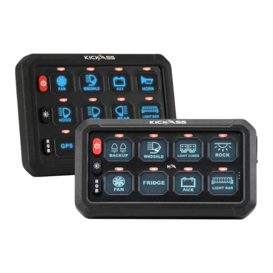
- Page 1 8/12 GANG WIRELESS 12V SWITCH PANEL OWNER’S MANUAL KAWLSWPANEL-8 I KAWLSWPANEL-12 V1.3...
-
Page 2: Table Of Contents
TABLE OF CONTENTS -------------------------------------------- SAFETY INFORMATION ------------------------------------- PRODUCT SPECIFICATIONS --------------------------------------- INCLUDED COMPONENTS -------------------------------------------- PRODUCT FEATURES --------------------------------------------- PRODUCT OVERVIEW ----------------------------------------- PRODUCT INSTALLATION -------------------------------------- 8 GANG WIRING DIAGRAM ---------------------------------- 8 CIRCUIT FUSE BLOCK ------------------------------------- 12 GANG WIRING DIAGRAM ---------------------------------------- 12 CIRCUIT FUSE BLOCK -------------------- SWITCH PANEL INSTALLATION DIAGRAM ---------------------... -
Page 3: Safety Information
THIS MANUAL AND THE SYSTEM IS INSTALLED AS PER THIS INSTALLATION INSTRUCTIONS. KICKASS RECOMMENDS THAT THE SYSTEM BE INSTALLED BY A SUITABLY QUALIFIED PERSON. DISCLAIMER: KICKASS accepts no liability for any injury, loss or property damage that may occur from the improper or unsafe installation or use of its products. - Page 4 5. Do NOT alter or disassemble the system under any circumstances. All services or repairs must be returned to KickAss for repair. Incorrect handling or reassembly may result in a risk of electric shock or fire and may void the unit warranty.
- Page 5 10 Do not use this product to control safety critical devices or those that could cause harm if operated remotely (for example fume exhaust fans or lifters). Only operate devices with moving parts when you have a clear line of sight to the moving parts.
-
Page 6: Product Specifications
PRODUCT SPECIFICATIONS KAWLSWPANEL-8 Specification 8 Gang Voltage 12V/24V DC Power 720W at 12V / 1440W at 24V Maximum Current 60A Total Operating Temperature -40°C to 85°C Standby Power <3mA Battery Rechargeable Operation Wireless Weight Dimensions 12.7 X 6.9 X 1.4 CM Certification... -
Page 7: Included Components
INCLUDED COMPONENTS ACCESSORIES QUANTITY DESCRIPTION Control Unit Switch Panel 5pc Mounting Bracket Set Switch Panel Dock Antenna Circuit Breaker 60A or 80A Zipties Switch Panel Sticker Sheet USB Charging Cable Antenna Mounting Pad 1pc Negative Cable, 2pc Positive Cable Accessories Signal Cable 2A Mini Fuse Tap 24 Pc Hardware Set Screw Driver... -
Page 8: Product Features
PRODUCT FEATURES • Operate your DC appliances remotely from a distance of 60 meters. • The battery charges fully in 2-3 hours and can last for an impressive 5-6 days. • The 8 Gang Switch Panel can handle up to 60A, and the 12 Gang Switch Panel can handle up to 80A at 12V or 24V. -
Page 9: Product Overview
PRODUCT OVERVIEW NOTE: Turn on the switch before using the switch panel. Turning off the switch will completely power down the switch panel, helping to prevent unnecessary battery drain. Wireless Pairing Switch Antenna Cable ON/OFF 5 Levels of brightness adjustments Background colors... -
Page 10: Product Installation
PRODUCT INSTALLATION 8 GANG WIRING DIAGRAM 8 CIRCUIT FUSE BLOCK CIRCUIT 1 CIRCUIT 2 CIRCUIT 3 CIRCUIT 4 CIRCUIT 5 CIRCUIT 6 CIRCUIT 7 CIRCUIT 8... -
Page 11: Circuit Fuse Block
12 GANG WIRING DIAGRAM 12 CIRCUIT FUSE BLOCK CIRCUIT 1 CIRCUIT 2 CIRCUIT 3 CIRCUIT 4 CIRCUIT 5 CIRCUIT 6 CIRCUIT 7 CIRCUIT 8 CIRCUIT 9 CIRCUIT 10 CIRCUIT 11 CIRCUIT 12... -
Page 12: Switch Panel Installation Diagram
SWITCH PANEL INSTALLATION DIAGRAM Flush Mount Adjustable Mounting CONTROL BOX INSTALLATION DIAGRAM Fixed Mount Flush Mount... -
Page 13: Switch Panel Installation
SWITCH PANEL INSTALLATION SETUP 1 Align the bracket with Tighten the flat head hole position screws Installation is done SETUP 2 Align the base plate with Tighten the base plate Put on the bracket hole position screws Tighten the bracket Tighten the bracket screws screws... -
Page 14: Control Box Installation
CONTROL BOX INSTALLATION FIXED MOUNT Align the bracket with Tighten the screws Mount to surface hole position FLUSH MOUNT Align the bracket with Tighten the screws Mount to surface hole position... -
Page 15: Wiring Method
WIRING METHOD Connect circuit breaker to positive terminal Connect circuit breaker to positive terminal Connect circuit breaker to positive terminal Connect circuit breaker to positive terminal Connect ACC to control box Connect ACC to control box Connect light to control box, and negative wires can Connect light to control box, and negative wires can be connected to the common cathode be connected to the common cathode... -
Page 16: Product Configuration
PRODUCT CONFIGURATION HOW TO PAIR SWITCH PANEL WITH CONTROL BOX Note: Our factory settings have already paired them for you. In normal circumstances, you don’t need to pair them again. However, if there are special circumstances where you need to re-pair, follow these steps SETUP 1 Power on the Control Box, press and hold the pairing button. -
Page 17: Using The Product
USING THE PRODUCT CONTROL MODE SETTINGS 1. CONSTANT LIGHT: Default constant light, you do not need to set it. 2. MOMENTARY MODE: Long press the brightness adjustment button for 1 second. When the red backlight flashes, it enters the Momentary setting state. Press the button you want to set (you can choose between 8 or 12 buttons for Momentary Mode), then press the... - Page 18 3. STROBE MODE Long press the brightness adjustment button for 1 second, and the red blacklight flashes. (note: this is the Momentary setting state, please refer to its specific steps) Then short press the brightness adjustment button. When the blue backlight flashes, it enters the Strobe setting state.
-
Page 19: Button Functions
BUTTON FUNCTIONS ON/OFF Switch with memory function, remember last setting automatically SHORT PRESS 5 level brightness adjustment (100%, 75%, 50%, 25%, 10%) LONG PRESS Enter the setting mode, and choose between momentary mode and strobe mode, long press again to exit the setting mode. SHORT PRESS Switch single color (loop from 1-8 in order) 1. -
Page 20: Troubleshooting
TROUBLESHOOTING 1. If the loads are not tuning On, It is always better to check the respective fuses on the control box as well as the circuit breaker 2. Always make sure that the connected battery's continuous discharge current supports powering up all your loads otherwise you either damage your battery or the battery goes into over-discharge current protection and shuts down your loads. -
Page 21: Frequently Asked Questions
FREQUENTLY ASKED QUESTIONS What is the maximum running current? The 8 Gang Switch Panel is rated for 60A, and the 12 Gang Switch Panel is rated for 80A. Can I the negative wire to the common cathode? Yes. How do I know if the wiring is correct? If the power indicator is red on, means the connection is correct. -
Page 22: Warranty And Support Information
The battery can support the switch panel under standby status for 833 days without charging. WARRANTY & SUPPORT INFORMATION Need help? For product support or to make a warranty claim, reach out to the KickAss Customer Service team on: warranty@kickassproducts.com.au Alternatively, visit our Customer Support Portal at: https://supportportal.kickassproducts.com.au/... - Page 23 KickAss is a registered trademark of KickAss Products Pty Ltd Designed & imported by KickAss Products Pty Ltd 39 Iris Place, Acacia Ridge, QLD 4110 Australia Made in China...
Need help?
Do you have a question about the KAWLSWPANEL-8 and is the answer not in the manual?
Questions and answers