
Related Manuals for Daikin FDXV41NVLT


Summary of Contents for Daikin FDXV41NVLT
- Page 1 Si071562E REMOVAL PROCEDURE S E R V I C E M A N U A L 4.1/5.0/6.3/7.1 kW Class Indoor Unit Inverter Duct Connected Type...
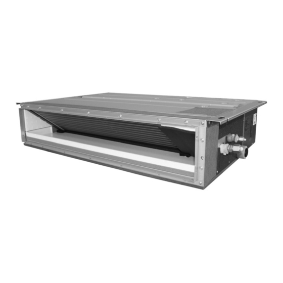
- Page 2 Service Manual Removal Procedure Indoor Unit Heat Pump FDXV41NVLT FDXV50NVLT FDXV63NVLT FDXV71NVLT CDXM50PVLT CDXM63PVLT CDXM71PVLT...
-
Page 3: Table Of Contents
Si071562E Table of Contents 1. Air Filter....................2 2. PCB......................4 3. Drain Pan ....................7 4. Indoor Heat Exchanger ................8 5. Thermistor ASSY ..................12 6. Fan Motor / Fan Rotor................13 Note: The illustrations may be slightly different depending on the model. Removal Procedure... -
Page 4: Air Filter
Air Filter Si071562E 1. Air Filter Warning Be sure to wait for 10 minutes or more after turning off all power supplies before disassembling work. Step Procedure Points 1. Remove the rear suction There are cases of rear type air filter. suction type and the bottom suction type filters. - Page 5 Si071562E Air Filter Step Procedure Points Press the 3 front hooks to unfasten them. (R22684) Hook Pull the air filter forward to unfasten the 3 back hooks and remove the air filter. Air filter (R22685) Hook Removal Procedure...
-
Page 6: Pcb
Si071562E 2. PCB Warning Be sure to wait for 10 minutes or more after turning off all power supplies before disassembling work. Step Procedure Points 1. Remove the electrical box Right side cover. Remove the 2 screws. (R22686) Lift up the electrical box When reassembling, make cover to unfasten the 2 sure that the 2 hooks are... - Page 7 Si071562E Step Procedure Points Disconnect the [S1], [S7]: fan motor [S1] connectors [S1] and [S7]. (R22689) [S7] Disconnect the [S26]: display PCB connectors [S26] and [S32]: indoor heat exchanger [S32]. thermistor [S32] [S26] (R22690) Cut the 2 clamps. Clamp (R22691) Removal Procedure...
- Page 8 Si071562E Step Procedure Points Unfasten the 3 bottom hooks. (R22692) Hook Pull the lower part of Hook the PCB forward to unfasten the 2 upper hooks. (R22693) Remove the PCB. (R22694) Removal Procedure...
-
Page 9: Drain Pan
Si071562E Drain Pan 3. Drain Pan Warning Be sure to wait for 10 minutes or more after turning off all power supplies before disassembling work. Step Procedure Points 1. Remove the bottom plate. The number of screws varies Bottom side depending on the model. -
Page 10: Indoor Heat Exchanger
Indoor Heat Exchanger Si071562E 4. Indoor Heat Exchanger Warning Be sure to wait for 10 minutes or more after turning off all power supplies before disassembling work. In pump-down work, be sure to stop the compressor before disconnecting the refrigerant pipe. If the refrigerant pipe is disconnected with the compressor operating and the stop valve open, air may be sucked in and may generate an over-pressure in refrigeration cycle, thus resulting in pipe rupture or accidental injury. - Page 11 Si071562E Indoor Heat Exchanger Step Procedure Points 2. Remove the indoor heat exchanger thermistor. Bottom side Cut the clamp. Clamp (R22701) Pull out the earth / ground connector. Earth / ground connector (R22702) Remove the 4 screws To prevent the indoor heat and remove the indoor exchanger from dropping, be heat exchanger...
- Page 12 Indoor Heat Exchanger Si071562E Step Procedure Points Cut the clamp. Clamp (R22704) Pull out the indoor heat The position of the indoor Indoor heat exchanger thermistor exchanger thermistor. heat exchanger thermistor varies depending on the model. Be careful not to lose the clip of the thermistor.
- Page 13 Si071562E Indoor Heat Exchanger Step Procedure Points Slide the refrigerant When reassembling, make Hook pipe supporting plate sure that the hook is downward to unfasten securely fastened. the hook and remove it. Hook (R22708) Refrigerant pipe supporting plate (R22707) Make sure to support Bottom side the indoor heat Indoor heat exchanger...
-
Page 14: Thermistor Assy
Thermistor ASSY Si071562E 5. Thermistor ASSY Warning Be sure to wait for 10 minutes or more after turning off all power supplies before disassembling work. Step Procedure Points Remove the 4 screws and remove the chamber cover. Chamber cover (R22711) Cut the 2 clamps and Hook release the thermistor... -
Page 15: Fan Motor / Fan Rotor
Si071562E Fan Motor / Fan Rotor 6. Fan Motor / Fan Rotor Warning Be sure to wait for 10 minutes or more after turning off all power supplies before disassembling work. Step Procedure Points 1. Remove the chamber You can remove the fan Bottom side cover. - Page 16 Fan Motor / Fan Rotor Si071562E Step Procedure Points 3. Remove the fan rotor assembly. Pull out the clamp (1) and cut the 2 clamps (2). Clamp (1) Clamp (2) (R22719) Shift the glass tube to the left and cut the clamp.
- Page 17 Si071562E Fan Motor / Fan Rotor Step Procedure Points Shift the glass tube and Glass tube disconnect the fan motor connector. (R22723) Fan motor connector Loosen the 2 screws. There is no hook around fan motor, always support the fan motor to prevent it from dropping off while loosening the screws.
- Page 18 Fan Motor / Fan Rotor Si071562E Step Procedure Points 4. Remove the fan motor. Use a hexagonal wrench key to remove the fan rotor fixing screw. (R22728) Remove the fan rotor from the fan rotor shaft. Fan rotor Fan rotor shaft (R22729) Use a hexagonal wrench key to remove...
- Page 19 Revision History Month / Year Version Revised contents 01 / 2016 Si071562E First edition...
- Page 20 Improper installation can result in water or refrigerant leakage, electrical shock, fire or explosion. Use only those parts and accessories supplied or specified by Daikin. Ask a qualified installer or contractor to install those parts and accessories. Use of unauthorised parts and accessories or improper installation of parts and accessories can result in water or refrigerant leakage, electrical shock, fire or explosion.
Need help?
Do you have a question about the FDXV41NVLT and is the answer not in the manual?
Questions and answers