
Related Manuals for Daikin FDXS25EV2C


Summary of Contents for Daikin FDXS25EV2C
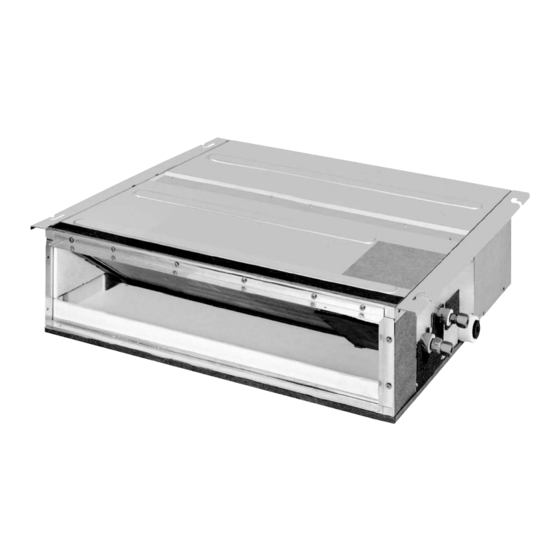
- Page 1 Si07-863 REMOVAL PROCEDURE S E R V I C E M A N U A L 2.5/3.5/5.0 kW Class Indoor Unit Inverter Duct Connected Type...
- Page 2 Service Manual Removal Procedure Indoor Unit Heat Pump FDXS25EV2C FDXS35EV2C FDXS50EV2C PDXS25EV2C PDXS35EV2C...
-
Page 3: Table Of Contents
Si07-863 Table of Contents 1. Removal of Air Filter................2 2. Removal of PCB (Room Air Conditioner Type)........4 3. Removal of Drain Pan ................6 4. Removal of Heat Exchanger ..............7 5. Removal of Fan Rotor / Fan Motor............10 6. Removal of Drain Pump Cover .............14 7. -
Page 4: Removal Of Air Filter
Removal of Air Filter Si07-863 1. Removal of Air Filter Procedure Warning Be sure to wait 10 minutes or more after turning off all power supplies before disassembling work. Procedure Points Step 1. Remove the air filter There are cases of rear suction type and the bottom Appearance suction type filters. - Page 5 Si07-863 Removal of Air Filter Step Procedure Points 3. Remove the bottom suction type air filter Air filter Appearance (Bottom suction type air filter) Undo 2 hooks as shown in the figure of the rear suction type (previous page). Undo the 2 positions in the opposite side of the hooks above.
-
Page 6: Removal Of Pcb (Room Air Conditioner Type)
Removal of PCB (Room Air Conditioner Type) Si07-863 2. Removal of PCB (Room Air Conditioner Type) Procedure Warning Be sure to wait 10 minutes or more after turning off all power supplies before disassembling work. Procedure Points Step 1. Remove the electrical box cover Remove the 2 screws from the upper area. - Page 7 Si07-863 Removal of PCB (Room Air Conditioner Type) Step Procedure Points 2. Remove the PCB Black Pull the Faston White terminals out from the terminal board with Green / Yellow pliers to remove them. 1: Black 2: White 3: Red Earth cable: Green / Yellow Disconnect the...
-
Page 8: Removal Of Drain Pan
Removal of Drain Pan Si07-863 3. Removal of Drain Pan Procedure Warning Be sure to wait 10 minutes or more after turning off all power supplies before disassembling work. Procedure Points Step 1. Remove the bottom plate Remove the 11 screws from the bottom plate. -
Page 9: Removal Of Heat Exchanger
Si07-863 Removal of Heat Exchanger 4. Removal of Heat Exchanger Procedure Warning Be sure to wait 10 minutes or more after turning off all power supplies before disassembling work. Procedure Points Step 1. Remove the heat Warning exchanger When any gas leakage is found, Make sure that the gases repair the gas leakage points. - Page 10 Removal of Heat Exchanger Si07-863 Step Procedure Points Cut one part in the clamp in the heat exchanger thermistor area. Remove the heat exchanger thermistor. Support the heat Note: exchanger to prevent it The Heat exchanger is fixed from dropping while you with these 4 screws (2 in the remove the 2 screws heat exchanger left side and...
- Page 11 Si07-863 Removal of Heat Exchanger Step Procedure Points Heat exchanger supporting plate Appearance before the heat exchanger is removed Remove the 2 screws from the refrigerant pipe supporting plate. Refrigerant pipe supporting plate Slide the refrigerant pipe supporting plate downward to remove it. Refrigerant pipe supporting plate Remove the heat exchanger.
-
Page 12: Removal Of Fan Rotor / Fan Motor
Removal of Fan Rotor / Fan Motor Si07-863 5. Removal of Fan Rotor / Fan Motor Procedure Warning Be sure to wait 10 minutes or more after turning off all power supplies before disassembling work. Procedure Points Step 1. Remove the protective grille Remove the 6 screws from the guard net. - Page 13 Si07-863 Removal of Fan Rotor / Fan Motor Step Procedure Points 3. Remove the chamber cover Remove the 4 screws from the chamber cover. Remove the chamber cover. Chamber cover 4. Remove the fan housings Press the 2 hooks at the fan assembly lower part to undo the hooks.
- Page 14 Removal of Fan Rotor / Fan Motor Si07-863 Step Procedure Points Remove the fan assembly lower part. (The procedure above applies to both right and left fan assembly.) 5. Remove the fan motor Cut 2 parts in the clamp. Shift the glass tube. Glass tube Disconnect the fan motor cable connector.
- Page 15 Si07-863 Removal of Fan Rotor / Fan Motor Step Procedure Points Remove the one screw Fan motor fixing plate from the fan motor fixing plate to remove the both right and left fan motors. 6. Remove the fan rotor Remark: To remove the fan rotor, it is Remove the fan rotor necessary to remove the fan...
-
Page 16: Removal Of Drain Pump Cover
Removal of Drain Pump Cover Si07-863 6. Removal of Drain Pump Cover Procedure Warning Be sure to wait 10 minutes or more after turning off all power supplies before disassembling work. Procedure Points Step 1. Remove the drain pump Remark: It is not necessary to remove Remove the one screw the PCB before you remove... -
Page 17: Removal Of Drain Pump
Si07-863 Removal of Drain Pump 7. Removal of Drain Pump Procedure Warning Be sure to wait 10 minutes or more after turning off all power supplies before disassembling work. Procedure Points Step 1. Remove the bottom plate Remove the 11 screws from the bottom plate. - Page 18 Removal of Drain Pump Si07-863 Step Procedure Points Pull the connector out. (X8A, X25A) Cut the clamp for fixing the rubber hose at the pump discharge side. Pull the drain hose out. Remove the 3 screws. Removal Procedure...
- Page 19 Si07-863 Removal of Drain Pump Step Procedure Points Hold the drain pump and pull out the electric wiring together with the heat insulating material. Heat insulating material Electric wiring Remove the drain pump. Removal Procedure...
-
Page 20: Removal Of Heat Exchanger Thermistors
Removal of Heat Exchanger Thermistors Si07-863 8. Removal of Heat Exchanger Thermistors Procedure Warning Be sure to wait 10 minutes or more after turning off all power supplies before disassembling work. Procedure Points Step 1. Remove the heat exchanger thermistors Cut 3 parts in the clamp. - Page 21 Revision History Month / Year Version Revised contents 06 / 2013 Si07-863 First edition...
- Page 22 Improper installation can result in water or refrigerant leakage, electrical shock, fire or explosion. Use only those parts and accessories supplied or specified by Daikin. Ask a qualified installer or contractor to install those parts and accessories. Use of unauthorised parts and accessories or improper installation of parts and accessories can result in water or refrigerant leakage, electrical shock, fire or explosion.
Need help?
Do you have a question about the FDXS25EV2C and is the answer not in the manual?
Questions and answers