
Related Manuals for Immergas 3.020166


Summary of Contents for Immergas 3.020166
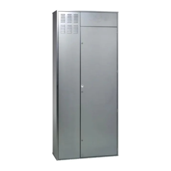
- Page 1 COD. 3.020166 KIT SOLAR Istruzioni e avvertenze CONTAINER KIT SOLAR Instruction and CONTAINER warning book...
-
Page 2: Avvertenze Generali
IL PRESENTE FOGLIO È DA LASCIARE ALL'UTENTE ABBINATO AL LIBRETTO ISTRUZIONI DEL PRODOTTO FINITO AVVERTENZE GENERALI. Tutti i prodotti Immergas sono protetti con idoneo imballaggio L’installazione o il montaggio improprio dell’ a pparecchio e/o dei da trasporto. componenti, accessori, kit e dispositivi Immergas potrebbe dare... - Page 3 (solo per installazione “tipo C”) mediante l’utilizzo di Magis Pro,Trio Pack e Trio Hydro in pareti esterne e interne. fumisteria marcata Immergas (da utilizzare solo in presenza di Il telaio nella sua parte inferiore è dotato dei fori necessari per caldaie).
- Page 4 DIMA ALLACCIAMENTO. ALLACCIAMENTO POMPA DI CALORE - ACC. INERZIALE - UNITA'ESTERNA VICTRIX HYBRID (Per dettagli quote vedi fig.1) ALLACCIAMENTO POSTERIORE ALLACCIAMENTO INFERIORE ALLACCIAMENTO LATERALE DESTRO Legenda: G - Alimentazione gas AC - Uscita acqua calda sanitario AF - Entrata acqua sanitario MHT - Mandata da pompa di calore RHT - Ritorno a pompa di calore MHT2 - Mandata da pompa di calore (Victrix Hybrid Plus)
- Page 5 TABELLA ALLACCIAMENTI ZONE. Zona Y Zona X Gaudium Solar Base V2 Zona 1 diretta Non utilizzata Gaudium Solar Plus Base V2 Trio V2 Zona 1 miscelata Zona 2 diretta Gaudium solar 2 zone V2 Zona 2 diretta Zona 1 diretta Gaudium solar Plus 2 zone V2 Trio Mono V2 Non utilizzata...
-
Page 6: Installazione
INSTALLAZIONE: Per i collegamenti elettrici è necessario separare la connessione Predisporre le opere murarie creando un'apertura nella parete alla rete elettrica dall’allacciamento alla termoregolazione facen- dove verrà installato il telaio (1), facendo attenzione a preve- do passare i relativi cavi nelle aperture previste. dere lo spazio per i sei spacchi per inserire le rispettive alette Effettuare l’allacciamento gas (dove richiesto). - Page 7 Legenda disegni installazione: Identificazione univoca componente Identificazione sequenziale operazione da svolgere Identificazione componente generico o non fornito in dotazione Fig. 4...
- Page 8 Fig. 5 Fig. 6 Fig. 7 Fig. 8...
-
Page 9: General Warnings
This instruction manual provides technical information for Installation and maintenance must be performed in compliance installing the Immergas kit. As for the other issues related to kit with the regulations in force, according to the manufacturer's in- installation (e.g. safety at the workplace, environmental protection,... -
Page 10: Kit Description
“C type” installations) and to the intake duct (only for “C space for the Gaudium Solar V2, Trio V2, Basic Magis Pro, Trio type” installation) using the Immergas flue (to be used only in Pack and Trio Hydro in external and internal walls. - Page 11 CONNECTION TEMPLATE. HEAT PUMP CONNECTION - INERTIAL STORAGE TANK - VICTRIX HYBRID OUTDOOR UNIT (For details of values see fig.1) REAR CONNECTION FLOW AND RETURN FOR INERTIAL STORAGE TANK LOWER CONNECTION RIGHT HAND SIDE CONNECTION Key: G - Gas supply AC - Domestic hot water outlet AF - DHW (Domestic hot water) water inlet MHT - Flow from heat pump...
- Page 12 ZONE CONNECTION TABLE. Zone Y Zone X Gaudium Solar Base V2 Zone 1 direct Not used Gaudium Solar Plus Base V2 Trio V2 Zone 1, mixed Zone 2, direct Gaudium solar 2 zone V2 Zone 2, direct Zone 1 direct Gaudium solar Plus 2 zone V2 Trio Mono V2 Not used...
-
Page 13: Installation
INSTALLATION: The electrical connections require the connection to the electric Set-up the masonry jobs creating an opening in the wall where mains to be separated from the connection to the temperature the frame will be installed (1), paying attention to envision the control by passing the relative cables through the openings space for the six slots for inserting the respective support fins provided. - Page 14 Drawings key installation: Unambiguous component identification Sequential identification of the operation to perform Identification of generic or not supplied component Fig. 4...
- Page 15 Fig. 5 Fig. 6 Fig. 7 Fig. 8...
- Page 16 Per richiedere ulteriori approfondimenti specifici, i Professionisti del settore possono anche avvalersi dell’indirizzo e-mail: consulenza@immergas.com To request further specific details, sector Professionals can also use the following e-mail address: consulenza@immergas.com Immergas S.p.A. 42041 Brescello (RE) - Italy Tel. 0522.689011 Fax 0522.680617...
Need help?
Do you have a question about the 3.020166 and is the answer not in the manual?
Questions and answers