Table of Contents
Advertisement
Quick Links
Advertisement
Table of Contents

Subscribe to Our Youtube Channel
Related Manuals for Rohde & Schwarz AMN6500


Summary of Contents for Rohde & Schwarz AMN6500
- Page 1 ® R&S AMN6500 Two Line V-Network User Manual (=Â<=2) 1352121302 Version 01...
- Page 2 Rohde & Schwarz GmbH & Co. KG. Trade names are trademarks of the owners. ® 1352.1213.02 | Version 01 | R&S AMN6500 Throughout this manual, products from Rohde & Schwarz are indicated without the ® symbol , e.g. R&S ® AMN6500 is indicated as R&S AMN6500.
-
Page 3: Safety And Regulatory Information
The product documentation helps you use the product safely and efficiently. Follow the instructions provided here and in the following chapters. Intended use The R&S AMN6500 Two Line V-Network is used to measure the unsymmetric disturb- ance voltage on AC mains and DC lines. Its principal tasks are: ●... - Page 4 ® Safety and regulatory information R&S AMN6500 Safety instructions LISNs are designed according to CISPR 16-1-2 (EN 55016-1-2) and do not meet the permissible limit for the leakage current as defined in EN 61010-1. In addition, LISNs do not provide basic insulation, rated as measurement category II (protection class 1).
- Page 5 ® Safety and regulatory information R&S AMN6500 Safety instructions without lifting it. The foldable feet are designed to carry the weight of the LISN, but not an extra load. Observe the applicable national regulations and standards as part of the installation process.
- Page 6 ® Safety and regulatory information R&S AMN6500 Safety instructions ● Ensure that you can disconnect the product from the power source at any time. Pull the power plug to disconnect the product. The power plug must be easily accessible. If the product is integrated into a system that does not meet these requirements, provide an easily accessible circuit breaker at the system level.
-
Page 7: Labels On The Product
® Safety and regulatory information R&S AMN6500 Warning messages in the documentation Warning: laser beam The product contains a laser. Avoid exposure to direct or reflected laser beam. 1.2 Labels on the product Labels on the casing inform about: ●... - Page 8 Preface R&S AMN6500 Introduction 2 Preface 2.1 Introduction The R&S AMN6500 Two Line V-Network is used to measure noise voltage on mains- dependent consumers. Its principal tasks are: ● To supply the equipment under test with mains voltage ● To provide a standardized load impedance ●...
-
Page 9: Block Diagram
The original pack- aging is also useful for use when shipping or transporting at a later date. Keep at least the two protective hoods for the front and rear to protect the R&S AMN6500 against damage to the control elements and connections. -
Page 10: Instrument Tour
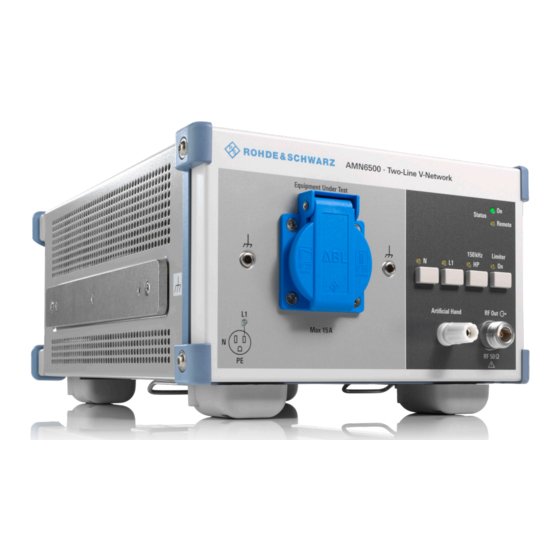
® Instrument tour R&S AMN6500 Front panel tour 3 Instrument tour 3.1 Front panel tour 1 = EUT Socket 2 = Reference ground connectors (4-mm-jacks) 3 = L1 LED, phase indicator 4 = ON LED 5 = Remote LED 6 = N key... - Page 11 Chapter 4.3, "Connecting to power", on page 15. ON LED (4) This LED shows that the R&S AMN6500 is powered up. Remote LED (5) This LED shows that a remote control function is active. See also Chapter 5, "Remote control", on page 23.
-
Page 12: Rear Panel Tour
® Instrument tour R&S AMN6500 Rear panel tour RF output connector (11) The "RF Output" socket is the RFI voltage measurement output for connecting the test receiver. The RFI voltage spectrum of the selected path is attenuated at the "RF Out- put"... - Page 13 Connection for the plug-in power supply. The control circuitry of the R&S AMN6500 is powered via the "External Power Supply" socket, if the R&S AMN6500 is to be used to conduct measurements of AC voltages below 90 VAC or on DC voltages up to 28 VDC.
-
Page 14: Preparing For Use
5. DANGER! Risk of electric shock. Before you connect the V-network to the power source, you have to connect the R&S AMN6500 to a protective ground terminal. An unearthed R&S AMN6500 is live. Touching a live electrical device causes serious personal injury, or even death. -
Page 15: Connecting To Power
2. Disconnect the auxiliary protective ground connection of the R&S AMN6500. 4.2 Connecting to protective ground Before the R&S AMN6500 is put into operation, the network must be connected to an additional conductor that is compliant with VDE0100. Users must be aware that it is possible for socket connections and grounding conduc- tors to become disconnected. - Page 16 4.4 Operating on non-standardized voltages For measurement tasks on voltages that are outside the normal mains voltage ranges (e.g. <90 VAC) and operation on DC (max. 28 VDC) the R&S AMN6500 control circuit is powered by an external power supply.
- Page 17 ® Preparing for use R&S AMN6500 Connecting to reference ground DIN/EN/IEC/UL/CSA 62368-1. An external power supply without reinforced/double insulation is live in case of failure. Touching a live electrical device causes serious personal injury, or even death. Connect the external power supply to the "EXT. POWER SUPPLY" socket (1).
-
Page 18: Connecting The Equipment Under Test
>35°C, external air ventilation is recommended. The RFI voltage measurement plane is located on the front panel of the R&S AMN6500. The impedance gradient of connections N and L1 of the socket is measured against the reference ground connectors (4-mm-jacks) to the left and right (2) of the socket (1). -
Page 19: Measurement Setup
AMN6500 Measurement setup 4.8 Measurement setup The R&S AMN6500 Two Line V-Network is suitable for measurments against CISPR, EN, VDE, ANSI, FCC Part 15 and MIL-STD-461 standards. The measurement setups prescribed in the individual standards are largely similar. A detailed description is provided for example by the standard CISPR 14-1 and EN 55014-1, see also the following figure. - Page 20 ® Preparing for use R&S AMN6500 Measurement setup 1 = Metal wall, at least 2 m x 2 m 2 = Equipment under test 3 = Cable in folded configuration 4 = Two-Line V-Network 5 = Shielded connection cable 6 = Test receiver...
-
Page 21: Sample Measurement
The figure in chapter 3, section entitled "Sample measurement" on the following page illustrates an example of how the foils are applied. HF disturbers on the supply line of the R&S AMN6500 may lead to interference vol- tages at the measurement output "RF Output". - Page 22 ® Preparing for use R&S AMN6500 Sample measurement 1 = Metal wall, at least 2 m x 2 m 2 = Equipment under test 3 = Connection cable 4 = Connection cable running separately to the hand simulation 5 = Two-Line V-Network...
-
Page 23: Remote Control
( L1 "ON" and 150 kHz HP "OFF") is always restored when mains power is switched on. The R&S AMN6500 is configured for direct connection to Rohde & Schwarz test receivers. If remote control is performed via an R&S receiver, the REMOTE LED is lit when the "ENV216"... - Page 24 ® Remote control R&S AMN6500 12 = GND 13 = TTL (+5V) 14 = N 15 = L1 18 = FLT User Manual 1352.1213.02 ─ 01...
-
Page 25: Maintenance, Storage And Disposal
Isolated parts, wiring insulation Plug connections and clamping points g) Vent and leakage paths must not be altered unacceptably. If any damage is detected, remove the R&S AMN6500 from the test environment and contact R&S customer support. See Chapter 6.2, "Contacting customer sup- port",... -
Page 26: Storage And Packaging
® Maintenance, storage and disposal R&S AMN6500 Disposal to find a solution to your query on any aspect of the operation, programming or applica- tions of Rohde & Schwarz products. Contact information Contact our customer support center at www.rohde-schwarz.com/support, or follow this QR code: Figure 6-1: QR code to the Rohde &... - Page 27 AMN6500 Annex A Country-specific connector models Germany as well as Australia, Finland, the Nether- lands, Norway, Russia, Sweden; Occasionally: Portugal, Spain R&S AMN6500 1352.1313.12 UK as well as Ireland, Hong Kong, Malaysia, Singa- pore R&S AMN6500 1352.1313.13 USA as well as Canada, Japan, Korea, Taiwan, Mex- ico, Central America R&S AMN6500...
Need help?
Do you have a question about the AMN6500 and is the answer not in the manual?
Questions and answers