Table of Contents
Advertisement
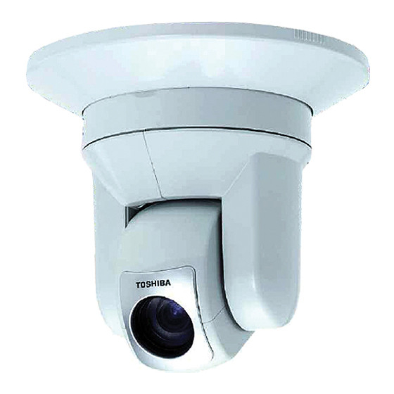
NETWORK CAMERA
: IK-WB21A
Model
Advanced User's Guide
For information on the latest products and peripheral devices, refer to
the following Web page.
■ http://www.netcam.toshiba.com
The above URL is subject to change without prior notice. If the URL
changes, refer to the Toshiba website
(http://www.toshiba.com).
Advertisement
Table of Contents

Subscribe to Our Youtube Channel
Related Manuals for Toshiba IK-WB21A


Summary of Contents for Toshiba IK-WB21A
- Page 1 Advanced User's Guide For information on the latest products and peripheral devices, refer to the following Web page. ■ http://www.netcam.toshiba.com The above URL is subject to change without prior notice. If the URL changes, refer to the Toshiba website (http://www.toshiba.com).
-
Page 2: Introduction
- Consult the dealer or an experienced radio/TV technician for help. Warning : Changes or modifications made to this equipment, not expressly approved by Toshiba or parties authorized by Toshiba could void the user's authority to operate the equipment. Canadian Information... -
Page 3: Table Of Contents
CD-ROM (x1) Quick Start Guide (x1) The instruction manual WARRANTY (x1) and software Camera Finder are contained. IK-WB21A Attachment for ceiling Cover for ceiling mounting (x1) mounting (x1) Using the ferrite core Screw set One ferrite core is supplied with the camera. Use Wood screws (x4) the core as illustrated below. -
Page 4: Table Of Contents
Table of Contents (Cont.) ● Recording Images on FTP Server ... 54 Record setting ... 54 ● ・ FTP Record Conditions ... 55 ・ FTP Server Settings - Server 1 ... 55 ・ FTP Server Settings - Server 2 ... 56 ・... - Page 5 IMPORTANT SAFEGUARDS (Cont.) 9. Ventilation This camera should never be placed near or over a radiator or heat register. This camera should not be placed in a built-in installation such as a bookcase or rack unless proper ventilation is provided or the manufacturer's instructions have been adhered to.
-
Page 6: Notes On Use And Installation
IMPORTANT SAFEGUARDS (Cont.) The CAUTION label, shown on the above part, is attached on the camera. The lightning flash with arrowhead symbol, within an equilateral triangle, is intended to alert the user to the presence of uninsulated "dangerous voltage" within the product's enclosure that may be of sufficient magnitude to constitute a risk of electric shock to persons. -
Page 7: Precautions For Use
SD memory card. The use of a 128, 256, or 512 MB, 1 GB large-capacity SD memory card is recommended for loop recording. ● To achieve maximum performance of the camera, the use of a Toshiba SD memory card is recommended. If a card of another company is used, the recording intervals may lengthen and the erasure time during overwriting may increase. -
Page 8: Overview Of The Network Camera
Overview of the Network Camera The IK-WB21A network camera can deliver video images and sound in real time using the Internet or an intranet. The camera is equipped with Ethernet (RJ- 45) 10BASE-T/100BASE-TX network interfaces. IK-WB21A can be used in various indoor environments. -
Page 9: Names Of Camera Parts
Names of Camera Parts Front Lens (Focal range: 0.4 inch to infinity) SD Card Cover Front Unfasten the screw in the SD card cover. SD Memory Card Slot Insert an SD memory card into the slot. Reset button Reset the settings to the defaults by using a thin, pointed object to press the button for at least 5 seconds. -
Page 10: When Installing On Ceiling
Installing the Camera (Cont.) Some provided parts are required for installing the camera. ● When installing on ceiling ・ Ceiling attachment ・ Cover for mounting on ceiling Important Improper installation may cause the camera to fall. ● ■ When installing on ceiling Make a hole in the ceiling where the camera is to be installed to insert the AC adapter cable, LAN cable and other cables. -
Page 11: Removing The Camera From The Ceiling Attachment
Installing the Camera (Cont.) Mount the camera on the ceiling attachment. ・ Align the four camera grooves with the ceiling attachment. ・ Push up on the camera firmly and slide the camera back until it is secure. ・ Mount the terminal cover. ・... -
Page 12: Connecting The Power Cord
Connecting the Power Cord Connect the power cord to the AC adaptor Remove the terminal cover on the camera and plug in the AC adapter plug into the power input terminal on the camera. Important Due to the compact space of the power terminal, ensure that the plug is ●... -
Page 13: Setting Network Camera Environment
Pentium III 800MHz or higher ・ Memory: 256MB or more ● Network camera (TOSHIBA network camera IK-WB21A) ・ Please purchase the required and appropriate number of cameras corresponding to the desired camera installation locations. ● Connection equipment such as a hub and router suiting the network system environment and LAN cable ・... -
Page 14: Ip Address
Connecting the Camera and Personal Computer by Network (Cont.) Connection Configuration Two configurations are available for connection of network cameras. ・Crossover connection ・Connection via a hub, switch, or router ●Using a crossover cable to establish a connection (example) Network camera IP address 192.168.0.30 LAN cable (crossover) -
Page 15: Using The Camera Search Application "Camera Finder
Operations that can be performed after log-in differ between administrator ● log-in and user log-in. (See page 30) Set the personal computer to "Administrator authorization" when using ● "Camera Finder." Important Toshiba is not responsible for any damages caused by this software. ●... -
Page 16: Administrator Log-In And User Log-In
Administrator Log-in and User Log-in This product regards a person who has performed Administrator Log-in as an "administrator" and a person who has performed User Log-in as a "user." Administrator Log-in can perform all functions, while the functions performed by User Log-in are limited. The following shows the different functions that are available for the administrator and the user. -
Page 17: Administrator Log-In Screen And User Log-In Screen
Administrator Log-in and User Log-in (Cont.) Administrator Log-in Screen and User Log-in Screen Administrator Log-in Screen Displays Camera Displays Displays Image screen Administrator Camera Setup Menu screen Image screen Exits Administrator Log-in screen When using Windows XP SP2 If clicking of the View button fails to display the Camera Image screen, operate as follows. -
Page 18: Viewing And Listening
Viewing and listening Viewing images Images of the network camera can be viewed through the Internet browser of your personal computer. ● Preparations before displaying ・ Enable cookies ・ Set "Browser setting when proxy server is used" on page 35 when a proxy server is used. -
Page 19: Audio
Viewing and listening (Cont.) ■ Audio Audio In from the network camera can be heard through the Audio Out of the personal computer. Set audio input to "ON" in "Camera/Audio setting" on page 79 and set the button of the Camera Image button to ■... -
Page 20: Controller
Viewing and listening (Cont.) ■ Controller ● Functions of components of Administrator basic controller Number and Item Description ① Operation Buttons Zoom : Zoom out button. Click to zoom out. : Zoom in button. Click to zoom in. Focus : Near button. For manual adjustment of the focus. Focuses on a near object. -
Page 21: Presetting Of Camera Position By Administrator
Viewing and listening (Cont.) Number and Item Description ⑦ The Auto Patrol feature moves the lens automatically to all the configured preset positions in order. Clicking button starts Auto Patrol. Clicking one of buttons stops the action. The Scan feature automatically moves (swivels) the lens horizontally back and forth once. -
Page 22: Selecting A Preset
Presetting of Camera Position by Administrator (Cont.) Selecting a Preset Selecting a preset from the list moves the camera to the preset position. In the list, click (go to Preset) button on the left of the preset you want to select. ・... -
Page 23: Setup Preset Items
Presetting of Camera Position by Administrator (Cont.) Setup Preset Items Set items in the detailed preset controller setup window that is displayed. Click button on the preset controller. The PAN/TILT Preset Settings screen will appear. Item setup. ■ Preset Name Settings ●... -
Page 24: Playing Recorded Alarm Images
Playing Recorded Alarm Images You can play images which are recorded when an alarm is activated. The images play at a fixed speed regardless of the recording setting. Image settings such as "Picture Resolution" correspond to Alarm recording settings. Click button while the Camera Image screen is displayed. -
Page 25: Playing External Control Recorded Images
Playing External Control Recorded Images External control recorded images recorded in an SD memory card can be replayed. (See page 52) The images play at a fixed speed regardless of the recording setting. Image settings such as "Picture Resolution" correspond to External Control recording settings. -
Page 26: Recording Images
About Recording Images Network camera can record images according to your need. Recordable media and its recordable contents are as follows. Recordable Media Recordable Contents SD Memory Card ・Alarm Recording images configured in "Alarm Recording" settings (→page 53). ・Continuous Recording images configured in "Continuous Recording"... -
Page 27: Alarm Recording
Recording Images in SD Memory Card (Cont.) Configure each setting items. ■ Alarm Recording ● Alarm In ON: Images are recorded when an external alarm occurs. OFF: Images are not recorded when an external alarm occurs. ● Ext. Control In ON: External control recording is performed. -
Page 28: Recording Images On Ftp Server
Recording Images on FTP Server By using FTP server, it becomes possible to manage periodic transferring and saving huge recorded image data. You can record images by "Scheduled Recording", "Alarm Recording" or "Ext. Control In Recording" on FTP server. Record setting Click "Camera Settings"... -
Page 29: Ftp Server Settings - Server 2
Recording Images on FTP Server (Cont.) ■ FTP Server Settings - Server 2 When using two servers for different purposes or on different occasions, enter the settings for the second server. ■ Transfer Image Size The size of images transferred to the FTP server can be set. NOTE The frame rate will be reduced if the "Transfer Image Size"... -
Page 30: Recording By Alarm
Recording Images on FTP Server (Cont.) ■ Recording by alarm (Displayed if "Alarm Recording" is chosen as an FTP record conditions.) Set if recording by Alarm In/Motion Detection is desired. ・ To detect external alarms or motion, set to enable "Alarm In" or "Motion Detection"... -
Page 31: Recording By Ext. Control In
Recording Images on FTP Server (Cont.) ■ Recording by Ext. Control In (Displayed if "Ext. Control In Recording" is chosen as an FTP record conditions.) Set if recording by Ext. Control In is desired. ・ Set to enable "Ext. Control In" in alarm setting (see page 73). 1) Setting a Recording Cycle ・... -
Page 32: File Transfer Order (Scheduled Recording)
Recording Images on FTP Server (Cont.) File Transfer Order (Scheduled Recording) Files are transferred in recorded order. However, these cameras may take following steps depending on network conditions. 1) When networking condition causes the file transferring delay, the camera may transfer the old files in the file transfer intervals. 2) Regardless of file transferring schedule, the camera continue to transferes files until all files are transfered. -
Page 33: Recording Sound In Personal Computer
Recording Sound in Personal Computer Sound can be recorded in a personal computer (wav file). Click button, one of the operation buttons in the Camera Image screen. ・ The setup screen for "Wave Local Saving" will appear. Set recording seconds or the number of files. Click the Seconds button or the Files button. -
Page 34: Camera/Basic Settings
Camera/Basic Settings Basic items such as size and quality of delivered images of the camera can be set. Click "Camera Settings" on the Admin. Menu. ・ A sub menu for Camera Settings will appear. Click "1. General" in the sub menu. ・... - Page 35 Camera/Basic Settings (Cont.) ● Auto B/W Configures Auto black and white function. Auto B/W is the func- tion to gain sensitivity by turning to B/W automatically when it becomes dark. The image may have some noise in B/W mode. ON: Auto B/W takes action. OFF:...
- Page 36 Camera/Basic Settings (Cont.) ● Slow Shutter Set a high limit value of the slow shutter. The camera sensitivity is maintained on an optimum image level between 1x and a set high limit value. Increasing the high limit value increases the camera sensitivity. NOTE Setting the high limit value of slow shutter other than to 1x automatically ●...
-
Page 37: Camera/Basic Settings, Frame Rate
Camera/Basic Settings, Frame Rate Set a frame rate (transfer rate, frames/s) of image data delivered to the network. Click "Camera Settings" on the Administrator Setup menu. ・ A sub menu for Camera Settings will appear. Click "1. General" in the sub menu. ・... -
Page 38: Camera/E-Mail Settings
Camera/Alarm Settings (Cont.) ● Alarm In/Ext. Control In 1) Set an "alarm" to be detected. Alarm In: Detects an external alarm. Ext. Control In: Performs external control. OFF: Does not perform "Alarm In" or "Ext. Control In." 2) Set "Input type" for alarms if "Function" is set to other than "OFF." Normally Opened (NO): A no-voltage contact system. - Page 39 Camera/E-mail Settings (Cont.) ● Authentication Settings 1) Choose "SMTP" or "POP" as the authentication system. 2) Enter an SMTP IP address or server name in "E-mail Server (SMTP)." 3) Enter the following when "POP" is chosen in authentication. "E-mail server (POP)": Enter an IP address or a server name of the POP server.
-
Page 40: Camera/Audio Settings
Camera/E-mail Settings (Cont.) ● E-mail Address List 1) Set ON or OFF in "Always Sent to Administrator E-mail Address." ON: Always send to administrator E-mail address. OFF: Not send to administrator E-mail address. 2) Enter "Mail-to Address." (Up to ten addresses) 3) Check send conditions. -
Page 41: Pan/Tilt Basic Settings
PAN/TILT Basic Settings Basic settings for PAN and TILT. Click "PAN/TILT Settings" in the Admin. Menu. ・ The sub menu for PAN/TILT Settings will appear. Click "1. General" in the sub menu. ・ A setup screen of "PAN/TILT - Basic Settings will appear. Configure each setting items. -
Page 42: Pan/Tilt Preset Settings
PAN/TILT Preset Settings Name assignment, position assignment, moving, deletion and other functions related to PAN and TILT can be set. Click "PAN/TILT Settings" in the Admin. Menu. ・ The sub menu for PAN/TILT Settings will appear. Click "2. Preset" in the sub menu. ・... -
Page 43: Pan/Tilt Auto Patrol
PAN/TILT Auto Patrol Dwell time for Auto Patrol can be set. Click "PAN/TILT Settings" in the Administrator Setup menu. ・ The sub menu for PAN/TILT setting will appear. Click "3. Auto Patrol" in the sub menu. ・ A setup screen of "PAN/TILT - Auto Patrol" will appear. Configure each setting items. -
Page 44: Network Basic Settings
Network Basic Settings An IP address and other items for connection to the network are set. Click "Network Settings" in the Admin. Menu. ・ The sub menu for Network Settings will appear. Click "1. General" in the sub menu. ・ A setup screen of "Network - Basic Settings" will appear. Configure each setting items. -
Page 45: Network/Ddns Settings
Network/DDNS Settings DDNS can be used. Establish DDNS server connection. Click "Network Settings" in the Admin. Menu. ・ The sub menu for network setting will appear. Click "2. DDNS" in the sub menu. ・ A setup screen of "Network / DDNS Settings" will appear. Configure each setting items. -
Page 46: Multi-Screen Display/Adding And Removing Cameras
Multi-Screen Display/Adding and Removing Cameras Cameras for displaying in the multi-view screen can be added. Click "Multi Screen Display" in the Admin. Menu. ・ The sub menu for multi screen display setting will appear. Click "1. Adding and Removing Cameras" in the sub menu. -
Page 47: Administrator Function/Changing Id And Password
Administrator Function/Changing ID and Password The administrator log-in name and password can be set. Click "Admin. Function" in the Admin. Menu. ・ The sub menu for administrator functions will appear. Click "1. Changing ID/Password" in the sub menu. ・ A setup screen of "Administrator Function / ID Password Change" will appear. -
Page 48: Admin Functions/User Operation Restriction Setting
Admin Functions/User Operation Restriction Setting Several setup items and operations can be made operable by users also. Click "Admin. Function" in the Admin. Menu. ・ The sub menu for administrator function will appear. Click "2. User Operation Restriction" in the sub menu. ・... -
Page 49: Version Updating (Administrator Function/Fw Update)
■ First step Download the latest firmware. ● Create a folder to save the latest firmware. ● Access the following Toshiba web site on the Internet: URL: http://www.netcam.toshiba.com ● Download the latest firmware in accordance with the Website. Do the following to update the firmware version. -
Page 50: Importing/Exporting Configuration Information (Administrator Function/Configuration Information)
Importing/Exporting Configuration Information (Administrator Function/Configuration Information) Camera configuration information (setup information) can be exported and saved in a personal computer ("Export") and can be imported from the personal computer ("import"). Exporting configuration information Click "Admin. Functions" in the Admin. Menu. ・... -
Page 51: Log Management (Log Management/Look Up And Delete)
Log Management (Log Management/Browse and Delete) The log display can be viewed and managed. See"Log display" on page 107 for data in log display. Click "Log Management" in the Admin. Menu. ・ The sub menu for Log Management will appear. Click "1. -
Page 52: Glossary (Index)
Alarm Terminals (Cont.) ■ Specifications of Alarm Signals Name Internal Circuit DC3.3V 47kΩ Alarm Input 220Ω Inside CMOS input Camera 220Ω Inside Alarm Output Camera CMOS Output ■ Example Circuit Connection Light Buzzer etc... Network Camera Door Sensor ALARM IN ALARM OUT Glossary (Index) Accessories ... - Page 53 Protocol). FTP, SMTP and other applications use TCP/IP. URL ... 27 (Uniform Resource Locator) Method for assigning the Internet resource. "http://www.toshiba. com/" is the example of when accessing a website on the Internet. User ... 32 Version updating ... 96 wav file ...
-
Page 54: Log Display
Log Display Logs are saved in the memory contained in the camera. Up to about 8000 logs can be saved. Output message 1110001 webm> Reset to default configuration. All settings are reset to configuration information at time of shipment from factory. 1121001 info>... - Page 55 Log Display (Cont.) Output message 2000517 upld> ...Updating fail. Camera rebooting was cancelled. 2000632 webm> Log was cleared. Cleared logs. 2000701 webm> Success to default. Camera info. Camera settings have been reset to factory preshipment inspection state. 2000705 webm> Success to default. Alarm info. FTP client settings have been reset to factory preshipment inspection state.
-
Page 56: Before Calling Service Personnel
Log Display (Cont.) Output message 3000322 apim> Called wblistnormal.cgi. API wblistnormal.cgi was booted. 3000323 apim> Called wblistextcontrol.cgi. API wblistextcontrol.cgi was booted. 3000341 apim> Called wbstoragestatus.cgi. API wbstragestatus.cgi was booted. 3000342 apim> Called wbstoragemount.cgi. API wbstragemount.cgi was booted. 3000343 apim> Called wbstoragemountstatus.cgi. API wbstragemountstatus.cgi was booted. - Page 57 Before Calling Service Personnel... (Cont.) Symptom Cause Error message shows up ●Entering wrong login ●Enter right login ID and password. when trying to login. ID and password. ※The default login ID is "root," and ●CapsLock of the PC ●The camera discriminates between is ON.
- Page 58 Before Calling Service Personnel... (Cont.) Symptom Cause Images are not colored. ●Auto B/W is set to ●Set auto B/W setting to OFF. ●Setting for color ●Increase color difference gain. difference gain is small. Cannot display images ●The Internet line is ●Wait for a little while.
- Page 59 Before Calling Service Personnel... (Cont.) Symptom Cause Cannot send mail. ●Settings of SMTP, ●Check your SMTP and POP server POP server may not be right. ●DNS server setting ●Set your DNS server from your may not be right. ※Sometimes "primary" is described ●Mail sending ●To send mail, you need to perform conditions are not...
-
Page 60: Specifications
● Designs and specifications may change without prior notice for better improvement. ● Screens, photos, illustrations and other diagrams contained in this user change from actual ones. IK-WB21A DC 12V ±10% (Use AC adapter supplied as an accessory) Approx.10W 1/4.2” CCD... -
Page 61: Appearance Diagram
Appearance Diagram Installed on desk 105.2 (4.142) 127.2 (5.008) 136 (5.354) (153 (6.024); maximum at the time of rotation) 66.5 (2.618) Unit : mm (inches) Installed on ceiling (0.945) 111.5 (4.39) 133.5 (5.256) 142.5 (5.61) 72.5 (2.854) φ172 (6.772) - Page 62 All risks associated with the quality or performance of these software components are assumed by the user. TOSHIBA shall not be liable whatsoever for any cost of repair or correction or other incidental expense incurred in connection with a defect found in any of these software components.
- Page 63 The original text (English) of end-user license agreement on free software components used in the TOSHIBA Network Camera (Cont.) 1. You may copy and distribute verbatim copies of the Program's source code as you receive it, in any medium, provided that you conspicuously and appropriately publish on each copy an appropriate copyright notice and disclaimer of warranty;...
- Page 64 The original text (English) of end-user license agreement on free software components used in the TOSHIBA Network Camera (Cont.) NO WARRANTY 11. BECAUSE THE PROGRAM IS LICENSED FREE OF CHARGE, THERE IS NO WARRANTY FOR THE PROGRAM, TO THE EXTENT PERMITTED BY APPLICABLE LAW. EXCEPT WHEN OTHERWISE STATED IN WRITING THE COPYRIGHT HOLDERS AND/OR OTHER PARTIES PROVIDE THE PROGRAM "AS IS"...
- Page 65 TOSHIBA AMERICA INFORMATION SYSTEMS. INC Security & Network Video Products 9740 Irvine Boulevard, Irvine California 92618-1697 Phone Number: (877)696-3822...
Need help?
Do you have a question about the IK-WB21A and is the answer not in the manual?
Questions and answers