
Related Manuals for Andover Controls CMX 240 Series


Summary of Contents for Andover Controls CMX 240 Series
- Page 1 CMX 240 Series Controller Installation Guide Andover Controls Corporation Technical Manuals Online! - http://www.tech-man.com firealarmresources.com...
- Page 2 IMPORTANT NOTICE This product is subject to change without notice. This document does not con- stitute any warranty, express or implied. Andover Controls Corporation re- serves the right to alter capabilities, performance, and presentation of this product at any time.
- Page 3 CMX controllers. It first presents site preparation informa- tion and then step-by-step installation instructions. We recommend you read Infinity Network Configuration Guide to plan your entire network before installing a single controller. Andover Controls Corporation Technical Manuals Online! - http://www.tech-man.com firealarmresources.com...
- Page 4 CMX 240 Installation Guide Technical Manuals Online! - http://www.tech-man.com firealarmresources.com...
-
Page 5: Table Of Contents
Building Ground Requirements .............6 Inspecting the Ground ..............7 Environmental Requirements ............8 Laying Out the Site Setup ..............8 Installing the CMX 240 Series Controller ..........9 Unpacking ..................9 Parts Required ................9 Mounting and Wiring ..............10 Connecting the AC Power Cable to the Power Supply ....13 Selecting the AC Input Voltage ...........14... - Page 6 Wiring Infinet to the CMX 240 ...........18 Wiring the TankNet and Probe Power Supply ......19 About the Safety Barriers ............21 Powering Up CMX 240 Series Controller ..........23 Connecting the Battery ..............24 Interpreting Status Lights Inside Cabinet ..........25 Custom Port Status Lights ............25 Communication Status Lights ............25...
- Page 7 Figure A-1. Pinouts for Cables Connecting to RS-232 Ports on Controller................... A-3 Figure B-1. Switch Settings for Switches 2 and 3 on Tank Probe ....B-2 Figure B-2. Switch Settings for Tank Probes on Channels 1 through 6 ..B-3 Andover Controls Corporation Technical Manuals Online! - http://www.tech-man.com firealarmresources.com...
- Page 8 Tables Table 1. Number of Infinet Controllers Allowed on Various CMX 240s ..............5 Table 2. AC Input Voltage Selection ..........14 Table A-1 Pinouts for RS-232 Comm Port with Male DB25 Connector to Terminal ............A-1 viii CMX 240 Installation Guide Technical Manuals Online! - http://www.tech-man.com firealarmresources.com...
-
Page 9: Installing The Cmx 240 Controller
From the CMX you can program the Infinet controllers. This manual covers the following: • Site/System Setup Requirements • Installing the CMX 240 series controller • Connecting to the Infinet • Connecting to the TankNet • Connecting to the Modem •... -
Page 10: Site/System Setup Requirements
Le présent appareil numérique n’émet pas de bruits radioélectriques dépassant les limites applicables aux appareils numériques de la class A prescrites dans le Règlement sur le brouillage radioélectrique édicté par le ministère des Communications du Canada. CMX 240 Series Installation Guide Technical Manuals Online! - http://www.tech-man.com firealarmresources.com... -
Page 11: Cabinet Dimensions
In the event repairs are ever needed on any Infinity CMX 240 controller, they should be performed by Andover Controls Corporation or an authorized representative of Andover Controls Corporation. For information contact Andover Controls at 300 Brickstone Square, Andover, Massachusetts 01810. -
Page 12: Power Requirements
Be sure your installation complies with local, state, and national electrical codes. Caution The CMX 240 series controller should receive power from its own independent, unswitched circuit. The CMX 240 requires 24/115/230 VAC +/-20%, 50/60 Hz rated at 30 VA with a modem and 20 VA without a modem. -
Page 13: Number Of Infinet Controllers On Cmx Infinet
Command mode on a terminal connected to COMM2. For details, see the Infinity Controller Programmer’s Guide. 1. You can also use any cables you may already have in place for ACNET or LBUS. CMX 240 Series Installation Guide Technical Manuals Online! - http://www.tech-man.com firealarmresources.com... -
Page 14: Tanknet And Probe Power Supply Cables
Two pair gas tube arrester, Andover Controls # 01-2100-299. Building Ground Requirements Warning Be sure that all Infinity products from Andover Controls Corporation are grounded to true earth ground. This kind of ground protects the equipment from voltage transients and other power surges in the area. -
Page 15: Inspecting The Ground
• Is connected to a corroded or galvanized pipe. • Is connected using a small gauge wire (less than 14 AWG). 2. Be sure your Andover Controls cabinet is connected to the ground with a copper conductor that terminates at the distribution panel. -
Page 16: Environmental Requirements
EnergyNet and Infinet Configuration Guide for information on how to design a configuration. You put only one CMX 240 series controller on an Infinet. You connect a terminal to the CMX. You cannot connect an LBUS to a CMX 240 series controller. You can- not have an Infinity CX 9000 controller on the same Infinet with any CMX 240. -
Page 17: Installing The Cmx 240 Series Controller
Parts Required To install a single controller you start with the following parts: • CMX 240 Series Controller • Cabinet (provided or other enclosure) • Modem (optional) • AC Power Cable •... -
Page 18: Mounting And Wiring
Mounting and Wiring Figure 1 shows the backplate and the positions of the eyelets for mounting the CMX 240 series controller. Warning Never drill holes in the CMX cabinet or boards. A metal shaving could easily short circuit the electronics. -
Page 19: Figure 1. Backplate With Dimensions And Eyelets For Mounting
Figure 1. Backplate with Dimensions and Eyelets for Mounting CMX 240 2.000 ± .015 8.550 4.275 Places 14.25 13.150 11.50 6.575 1.58 11.72 ± .03 12.54 ± .05 CMX 240 Series Installation Guide Technical Manuals Online! - http://www.tech-man.com firealarmresources.com... -
Page 20: Figure 2. Cabinet With Dimensions And Eyelets For Mounting
( 1 ) THIS DEVICE MAY NOT CAUSE HARMFUL INTERFERENCE, AND ( 2 ) THIS DEVICE MUST ACCEPT ANY INTERFERENCE RECEIVED, INCLUDING SERVICE INTERFERENCE THAT MAY CAUSE PORT UNDESIRED OPERATION. F6, 1/8A CMX 240 Series Installation Guide Technical Manuals Online! - http://www.tech-man.com firealarmresources.com... -
Page 21: Connecting The Ac Power Cable To The Power Supply
Figure 3. Metal Plate and Screw for Power Supply Wire Metal Plate Insert Wire Here 5. Place the white wire under the metal plate behind the middle screw, labeled NEU. CMX 240 Series Installation Guide Technical Manuals Online! - http://www.tech-man.com firealarmresources.com... -
Page 22: Selecting The Ac Input Voltage
E3 to E7. 2. Disconnect the jumper from E4 and connect it to E6, so it jumpers E2 to E6. 3. Leave the jumper P2 to E1 as it is. CMX 240 Series Installation Guide Technical Manuals Online! - http://www.tech-man.com firealarmresources.com... -
Page 23: Finding Ports For Connecting Other Cables
It is located just above COMM1, on the left side of the board. Communications Port Notice that the CMX 240 series controller has two RS-232 communica- tion ports, labeled COMM1 and COMM2 on the left side of the board. You can attach a cable to each port. -
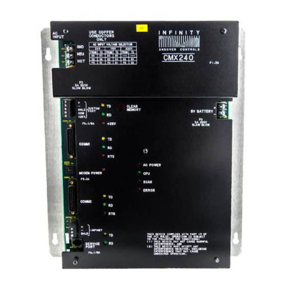
Page 24: Figure 4. Locations Of Ports And Connectors On The Cmx 240 Face Plate
( 1 ) THIS DEVICE MAY NOT CAUSE HARMFUL INTERFERENCE, AND ( 2 ) THIS DEVICE MUST ACCEPT ANY INTERFERENCE RECEIVED, INCLUDING SERVICE INTERFERENCE THAT MAY CAUSE PORT UNDESIRED OPERATION. F6, 1/8A CMX 240 Series Installation Guide Technical Manuals Online! - http://www.tech-man.com firealarmresources.com... -
Page 25: Connecting The Terminal Screen
Connecting the Terminal Screen Connect the terminal or computer (running a terminal emulation pack- age such as CROSSTALK) to the CMX 240 series controller as follows: 1. Set up the terminal or computer on a table within cable’s length of the controller. -
Page 26: Wiring Infinet To The Cmx 240
The end of the Infinet cable has two wires and a shield. You wire them to the block terminal connector on the Infinet port. 2. String the cable through the cable hole on the left side of the controller. CMX 240 Series Installation Guide Technical Manuals Online! - http://www.tech-man.com firealarmresources.com... -
Page 27: Wiring The Tanknet And Probe Power Supply
Wiring the TankNet and Probe Power Supply You connect the TankNet and probe power supply cables to a special port on the CMX 240 series controller called the CUSTOM PORT. Figure 7 illustrates how to wire TankNet and probe power supply cables to the CUSTOM PORT. -
Page 28: Figure 7. Attaching The Tanknet And Probe Power Supply Cables
To connect the probe power supply cable to the CUSTOM PORT use the following procedure: 1. Trim back the shield over the wires. 2. Slip the common wire through the hole beneath the screw labeled COM. CMX 240 Series Installation Guide Technical Manuals Online! - http://www.tech-man.com firealarmresources.com... -
Page 29: About The Safety Barriers
The two different Stahl intrinsic safety barriers are listed below: • Stahl intrinsic safety barrier model 8901/32-093/135/70 for the communications circuit • Stahl intrinsic safety barrier model 8901/31-280/165/80 for the power supply circuit CMX 240 Series Installation Guide Technical Manuals Online! - http://www.tech-man.com firealarmresources.com... -
Page 30: Figure 8. Diagram Of Safety Barrier Connection
To Probe Communications Negative Wire Intrinsic Safety Barrier Shield Ground Probe Power Supply +26V Power Supply To Probe Intrinsic Safety Barrier To Custom Port Common Shield Safe Area Hazardous Area CMX 240 Series Installation Guide Technical Manuals Online! - http://www.tech-man.com firealarmresources.com... -
Page 31: Powering Up Cmx 240 Series Controller
1. The CPU light begins flashing and flashes every 0.2 sec. 2. The TD lights immediately start flashing to show COMM1, COMM2, the CUSTOM PORT, or the Infinet is transmitting data. CMX 240 Series Installation Guide Technical Manuals Online! - http://www.tech-man.com firealarmresources.com... -
Page 32: Connecting The Battery
CMX 240 board, to the battery as follows: 1. Find the black and red battery wires that are already attached to the right side of the CMX 240 series controller labeled 6V BATTERY. 2. Take the negative black wire from the controller and slip it onto the black socket on the battery. -
Page 33: Interpreting Status Lights Inside Cabinet
-- - Communication Status Lights Three communication port status lights display to the right of COMM1 and COMM2. Figure 10 shows how the lights appear for each comm port. CMX 240 Series Installation Guide Technical Manuals Online! - http://www.tech-man.com firealarmresources.com... -
Page 34: Infinet Status Lights
INFINET (Green) The different colored lights flash to indicate the following: • TD (Yellow)—Flashes when the Infinet is transmitting data. • RD (Green)—Flashes when the Infinet is receiving data. CMX 240 Series Installation Guide Technical Manuals Online! - http://www.tech-man.com firealarmresources.com... -
Page 35: Modem Power Light
• CPU—Flashes every 0.2 sec that the controller is active. • SCAN—Flashes once for every scan of the controller. • ERROR—Lights up if the controller fails the internal integrity check. CMX 240 Series Installation Guide Technical Manuals Online! - http://www.tech-man.com firealarmresources.com... -
Page 36: Using The Clear Memory Button
Connecting the Andover Controls Service Tool The SERVICE PORT, on the lower left corner of the controller, is to connect the Andover Controls Service Tool to any CMX 240. The ser- vice tool will access all Infinet controllers on the same Infinet. For information on availability of the Andover Controls Service Tool, con- tact your Andover Controls representative. -
Page 37: Rs-232 Port Pinouts
However, to connect any terminal to a controller, you should use a cable with the required pinouts. This appendix shows the required pinouts. CMX 240 Series Installation Guide Technical Manuals Online! - http://www.tech-man.com firealarmresources.com... -
Page 38: 240 Controller
"Modem" means it is required for the modem. Figure A-1 shows the required and optional pinouts for cables connecting a terminal to the controller, a modem to the controller, and a modem to the terminal. CMX 240 Series Installation Guide Technical Manuals Online! - http://www.tech-man.com firealarmresources.com... -
Page 39: Figure A-1. Pinouts For Cables Connecting To Rs-232 Ports On
Figure A-1. Pinouts for Cables Connecting to RS-232 Ports on Controller Directly Connected Terminals or Workstations Female End Female End Connecting to VT 100 Connecting to or IBM PS/2 (25-pin) Controller Female End Female End Connecting to Connecting to IBM AT (9-pin) Controller Connected Over Modem Female End... - Page 40 CMX 240 Series Installation Guide Technical Manuals Online! - http://www.tech-man.com firealarmresources.com...
- Page 41 The DIP switch is located inside the probe head. For details on how to access the DIP switch, refer to the MTS installation guide supplied with the probe. CMX 240 Series Installation Guide Technical Manuals Online! - http://www.tech-man.com firealarmresources.com...
-
Page 42: Figure B-1. Switch Settings For Switches 2 And 3 On Tank Probe
Hardware Installation Set the tank probe switches as follows: 1. Set the second and third switches to ON for Andover Controls software. If they are not ON (enabled), you do not see error messages. Figure B-1 shows the settings for switches 2 and 3 on the probe. - Page 43 1 2 3 4 5 6 7 8 9 Channel 5 (Address 4) 1 2 3 4 5 6 7 8 9 Channel 6 (Address 5) 1 2 3 4 5 6 7 8 9 CMX 240 Series Installation Guide Technical Manuals Online! - http://www.tech-man.com firealarmresources.com...
- Page 44 Hardware Installation CMX 240 Series Installation Guide Technical Manuals Online! - http://www.tech-man.com firealarmresources.com...
- Page 45 AC power cabinet 3 wiring 13 controller 3 AC Power light inside 27 AC voltage setting 14 ERROR light inside 27 Andover Controls Service Tool using 28 features unique to CMX 240 1 barrier connection 22 ground correcting 7 cabinet...
- Page 46 modem safety barrier baud rate of 4 connection 22 mounting SCAN light inside 27 steps to 10 service port location of 15 purpose of 28 shields parts for Infinet cable inside the controller 15 connecting 19 requirements 9 status lights power requirements 4 communication ports 25, 26 circuit 4...
- Page 47 wiring connecting Infinet cable 19 correct wire gauge for ground 7 intrinsic safety barriers 21 CMX 240 Installation Guide Index-3 Technical Manuals Online! - http://www.tech-man.com firealarmresources.com...
- Page 48 Index-4 CMX 240 Installation Guide Technical Manuals Online! - http://www.tech-man.com firealarmresources.com...
- Page 49 30-3001-391 CMX 240 Series Controller Installation Guide Rev D Technical Manuals Online! - http://www.tech-man.com firealarmresources.com...
Need help?
Do you have a question about the CMX 240 Series and is the answer not in the manual?
Questions and answers