Sign In
Upload
Manuals
Brands
Andover Controls Manuals
Controller
CMX 240 Series
Andover Controls CMX 240 Series Manuals
Manuals and User Guides for Andover Controls CMX 240 Series. We have
1
Andover Controls CMX 240 Series manual available for free PDF download: Installation Manual
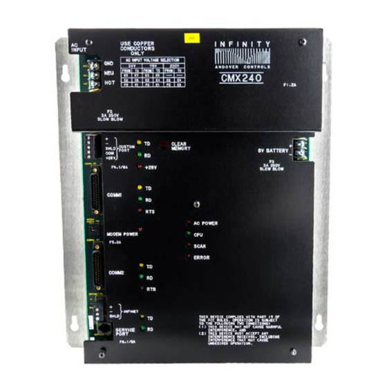
Andover Controls CMX 240 Series Installation Manual (49 pages)
Brand:
Andover Controls
| Category:
Controller
| Size: 1 MB
Table of Contents
Table of Contents
5
Installing the CMX 240 Controller
9
Site/System Setup Requirements
10
Cabinet Dimensions
11
Controller Dimensions
11
Power Requirements
12
Modem
12
Infinet Cables
12
Number of Infinet Controllers on CMX Infinet
13
Tanknet and Probe Power Supply Cables
14
Lightning Protection
14
Building Ground Requirements
14
Inspecting the Ground
15
Environmental Requirements
16
Laying out the Site Setup
16
Installing the CMX 240 Series Controller
17
Unpacking
17
Parts Required
17
Mounting and Wiring
18
Figure 1. Backplate with Dimensions and Eyelets for Mounting
19
Figure 2. Cabinet with Dimensions and Eyelets for Mounting
20
Connecting the AC Power Cable to the Power Supply
21
Figure 3. Metal Plate and Screw for Power Supply Wire
21
Selecting the AC Input Voltage
22
Finding Ports for Connecting Other Cables
23
Figure 4. Locations of Ports and Connectors on the CMX 240 Face Plate
24
Connecting the Terminal Screen
25
Connecting to the Infinity Modem
25
Wiring Infinet to the CMX 240
26
Figure 5. Jumpering P1 Pins for CMX 240, Top View
26
Wiring the Tanknet and Probe Power Supply
27
Figure 6. Infinet Cable Wiring
27
Figure 7. Attaching the Tanknet and Probe Power Supply Cables
28
About the Safety Barriers
29
Figure 8. Diagram of Safety Barrier Connection
30
Powering up CMX 240 Series Controller
31
Connecting the Battery
32
Interpreting Status Lights Inside Cabinet
33
Custom Port Status Lights
33
Communication Status Lights
33
Figure 9. Custom Port Status Lights
33
Infinet Status Lights
34
Figure 10. Communication Status Lights for Comm1
34
Figure 11. Communication Status Lights for Infinet
34
Modem Power Light
35
System Activity Status Lights
35
Figure 12. System Activity Status Lights
35
Using the CLEAR MEMORY Button
36
Connecting the Andover Controls Service Tool
36
RS-232 Port Pinouts
37
240 Controller
38
Figure A-1. Pinouts for Cables Connecting to RS-232 Ports on
39
Figure B-1. Switch Settings for Switches 2 and 3 on Tank Probe
42
Advertisement
Advertisement
Related Products
Andover Controls CMX 220
Andover Controls Infinity CX 9000
Andover Controls Infinity CX 9500
Andover Controls Continuum DI-6 AC
Andover Controls CONTINUUM
Andover Controls CONTINUUM NetController
Andover Controls ACX 780
Andover Controls ACX 781
Andover Controls DCX 250
Andover Controls Infinity
Andover Controls Categories
Controller
I/O Systems
Control Unit
IP Access Controllers
Power Supply
More Andover Controls Manuals
Login
Sign In
OR
Sign in with Facebook
Sign in with Google
Upload manual
Upload from disk
Upload from URL