Transcell Technology TI-500E Manual
Hide thumbs
Also See for TI-500E:
- Troubleshooting manual (10 pages) ,
- Setup & operation manual (5 pages)
Table of Contents
Advertisement
Quick Links
Advertisement
Table of Contents

Related Manuals for Transcell Technology TI-500E


Summary of Contents for Transcell Technology TI-500E
- Page 1 MODEL TI-500E Manual Digital Weight Indicator Version 1.22S June 28, 2022...
-
Page 2: Table Of Contents
© Transcell Technology, Inc. 2009-2022. All rights reserved. The information contained herein is the property of Transcell Technology and is supplied without liability for errors or omissions. No part may be reproduced or used except as authorized by contract or other written permission. The copy- right and the foregoing restriction on reproduction and use extend to all media in which the information may be embod- ied. -
Page 3: Display & Keypad Details
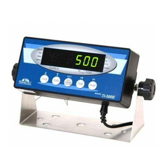
DISPLAY & KEYPAD DETAILS This indicator uses a 6-digit LED (Light Emitting Diode) display. The Table below summarizes the display annunciators. Annunciator Display Indication GROSS The indicator is in Gross Weight mode. The indicator is in Net Weight mode. TARE Indicates that a tare weight has been established in the system. - Page 4 The keypad comprises five (5) function keys. Marking Keypad Function Units Selects the displayed unit of measure, i.e., lb or kg. This key can be disabled. Zero Zeroes the weight display reading, provided certain conditions are met Net/Gross Selects the weighing mode, i.e., Gross weight or Net Weight. Tare Establishes a system Tare, provided certain conditions are met Print...
-
Page 5: Installation & Overview
INSTALLATION & OVERVIEW Remember that the installer is ultimately responsible to assure that a particular installation will be and remain safe and operable under the specific conditions encountered. The indicator must be properly configured and calibrated prior to use. Installation Find a suitable location for the indicator and use the included bracket to mount the unit to a wall or table. -
Page 6: Getting Started
The indicator features one full duplex RS-232 serial (COM) port, designed for connection to a computer or a serial printer. The same port may be also used as a simplex, RS-232 port de- signed for connection to a remote display. DSUB9 Connector Pin No. -
Page 7: Indicator Configuration
INDICATOR CONFIGURATION Configuration Menus The TI-500E contains two (2) menus to configure the indicator: Setup (“F”) Menu – Configures all metrologically-related parameters including calibration proce- dures. User (“A”) Menu – Configures communication parameters and other misc. parameters, e.g., Units key behavior. -
Page 8: Setup ("F") Menu Descriptions
6. If there is a selection list, scroll thru the available parameter settings, use the TARE (left) or PRINT (right) keys. Otherwise, use the arrow keys to adjust the displayed value to the new value. 7. Once the setting you want is displayed on the screen, press the NET/GROSS (set) key to save this value. -
Page 9: Entering The User ("A")
CODE/NAME DESCRIPTION SELECTION LIST Sets the interval value. Use together with F10. 1 Display Divisions Sets the decimal point value. Use together with F9. 0 Decimal Pt. 0.00 0.000 0.0000 Places indicator into live zero-calibration mode. Scrolling down with Press ZERO key Zero Calibra- the ZERO key one level begins the procedure. -
Page 10: User ("A") Menu Descriptions
7. If there is a selection list, scroll thru the available parameter settings, use the TARE (left) or PRINT (right) keys. Otherwise, use the arrow keys to adjust the displayed value to the new value. 8. Once the setting you want is displayed on the screen, press the NET/GROSS (set) key to save this value. -
Page 11: Exiting The Menus
CODE/NAME DESCRIPTION SELECTION LIST Allows the ID number to be disabled in the Print Ticket mode. Valid 0 only when A6 is set to “1”. ID No. Enable "0" = Disable the ID No. "1" = Enable the ID No. 0 –... -
Page 12: Indicator Calibration
INDICATOR CALIBRATION Calibration Overview There are two ways to calibrate the instrument: 1. Live calibration: You will be calibrating a scale platform to the indicator using actual loads, e.g., test weights. In general, this is the most accurate and dependable method of the two. - Page 13 If the calibration was not successful, one of the following error messages will appear. • "Err0" - The calibration test load or the keyed-in load is larger than the full capacity of the indicator. Change the calibration test load or check the input data. •...
-
Page 14: Advanced Operation
ADVANCED OPERATION Piece Counting Mode This mode is used to calculate (“count”) the number of items (parts) you have placed onto the scale platform. To ensure accuracy, the items you wish to count must be consistent in weight. To activate this mode, set F24 to “1” in the Setup Menu. The indicator uses the sampling to determine the average piece weight (APW) of the items you wish to count. -
Page 15: Serial (Com) Port Information
SERIAL (COM) PORT INFORMATION SERIAL PORT MODES DEMAND DUPLEX MODE The Demand Duplex Mode provides a two-way serial transmission mode. In this mode, the output information is transmitted on demand; either by pressing the PRINT key or upon receiving a recognized command from a host. NOTE: Ensure that your cabling has a crossover (null modem) and contains the proper handshaking lines. -
Page 16: Output Strings
OUTPUT STRINGS Text Print Ticket [A6 = “1” or “2” and A3 = “d”] The Text Print Ticket is designed specifically for a serial line printer. GROSS 1000.0 lb Use the following parameter settings to customize further: • A7: ID Number •... - Page 17 6L, 6P, 6LB, 6PB and CUSTOM Strings [A6 = “3”, “4”, “5”, “6” or “7”] These strings are designed for communication with the TSC TDP-225 serial printer...
-
Page 18: Specifications
SPECIFICATIONS Indicator Specifications Enclosure: ABS enclosure (IP54) Display: 0.56" (14 mm) 7-segment, LED, 6 Digit A-to-D converter: AD-01 Resolution: Approximately 200,000 counts @ 3mV/V input Sampling Rate: 10 Hz Excitation Voltage: +5 VDC, 4 x 350Ω load cells Input Signal Range: ±3.125 mV/V Serial Port: Full Duplex RS-232C Operating Temperature: 14°F to 104°F (-10°C to 40°C) Power... -
Page 19: Troubleshooting
(12) months from the date of purchase. For complete war- ranty details and service information, please contact us at the address below. Contents subject to change without notice. Transcell Technology, Inc. 975 Deerfield Parkway Buffalo Grove, IL 60089 847.419.9180...
Need help?
Do you have a question about the TI-500E and is the answer not in the manual?
Questions and answers