
Subscribe to Our Youtube Channel
Related Manuals for Transcell Technology TI-700K


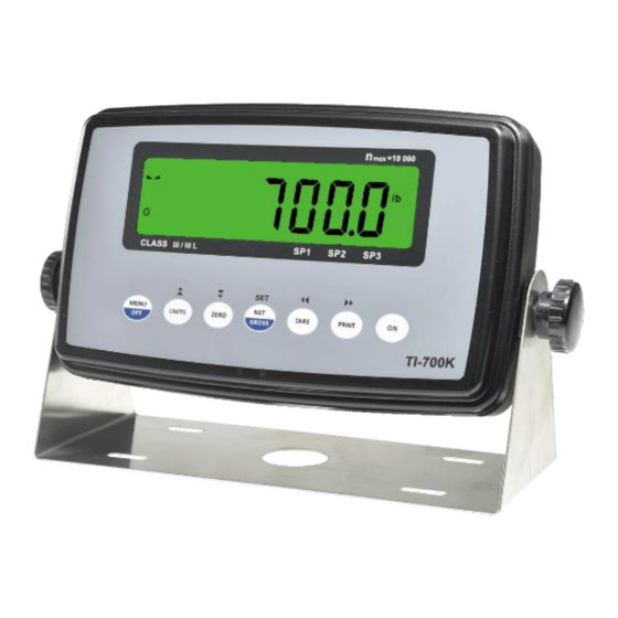
Summary of Contents for Transcell Technology TI-700K
- Page 1 MODEL TI-700K Installer’s Manual Digital Weight Indicator (with wireless weighing capability) Revision 1.7a March 09, 2020...
-
Page 2: Table Of Contents
©Transcell Technology, Inc. 2016-2020. All rights reserved. The information contained herein is the property of Transcell Technology and is supplied without liability for errors or omissions. No part may be reproduced or used except as authorized by contract or other written permission. The copy- right and the foregoing restriction on reproduction and use extend to all media in which the information may be embod- ied. -
Page 3: Installation & Overview
A factory installed rechargeable battery option is also available. Scope of TI-700K Out of the box, the TI-700K indicator operates as a basic, cabled digital weight indicator. The load cell(s) and/or j-box is connected to the indicator’s internal A/D convertor. This configuration is depicted in the following diagram: When sold as part of a Smarter Weigh™... -
Page 4: Installation Of Ti-700K Digital Indicator
This manual covers installation, configuration and calibration of the RF scale system. For opera- tion and troubleshooting, please refer to the separate user’s guide. Installation of TI-700K digital indicator Find a suitable location for the indicator and use the included bracket to mount the unit to a wall or table. - Page 5 Load Cell Connections Connect your shielded load cell cable to terminal block J1 using the table below. All terminals are labeled for function. TIP: You should have the color codes handy for your load cell / junction box / weighing platform before doing so.
-
Page 6: Rs-232 Connections (Com1)
Signal Ground Power Connections (AC version) The TI-700K indicator ships with a pre-installed AC line cord. It has been pre-wired to Terminal Block J1 at the factory. Simply plug the unit into a standard wall outlet. Power Connections (Optional Rechargeable Battery version) The TI-700K with rechargeable battery ships with a pre-installed battery charger connector and an external battery charger. -
Page 7: Usb Port
To prolong battery life, disconnect the external battery charger from the unit when charg- ing is complete (Green LED). Caution: the external battery charger is rated for IP54 only and exposure to water may void the warranty. Be sure to remove the battery charger from the indicator and apply the cap to the battery charger connector before washing it down. - Page 8 Electrical Connections The TI-500 RFTM module requires an external 6VDC power supply. Single channel units re- quire about 60 mA of current to drive four 350-ohm load cells (20 mA plus 10 mA per load cell). Dual channel units require about 100 mA of current to drive eight 350-ohm load cells. The TI-500 RFTM module will operate normally down to approximately 4 VDC whereupon it will indicate a low battery condition.
-
Page 9: Installation Of Lct-1 Remote Wireless Digital Junction Box
Installation of LCT-1 remote wireless digital junction box Physical installation Find a suitable location for the digital junction box and use the mounting tabs to mount the unit to a wall or table. The junction box may be mounted vertically or horizontally. Use this handy guide for mounting the box to a wall or table:... - Page 10 Electrical Connections The top cover must first be removed to make the appropriate connections to the weigh platform. To remove the top cover, simply remove the six (6) screws that secure it to the enclosure and set aside. Caution! Disconnect power source from junction box prior to removing top cover. Note: If the optional control panel was ordered, you need not make connections to the LCT-1 for power supply, serial device or on/off control Connecting your load cell(s)
-
Page 11: Getting Started - Cabled Systems
Connect your load cell cable (not included) to the appropriate terminal on the main board. Caution! Strip each load cell wire back 10 mm and tin before inserting into the spring- loaded terminals. Load Cell Terminals (J1, J5, J6 and J7) Label Function - Signal... -
Page 12: System Configuration
SYSTEM CONFIGURATION Configuration Menus The TI-700K digital indicator contains three menus to configure the scale system: Setup (“F”) Menu – Configures all scale-related parameters including calibration procedures. User1 (“A1”) Menu – Configures COM1 communication parameters and other misc. parameters, e.g. automatic turn off and hold mode. -
Page 13: Entering The Setup ("F") Configuration Menu
Entering the Setup (“F”) Configuration Menu To access this menu, please follow these directions: 1. Press and hold the MENU/OFF key to switch off the digital indicator. 2. Press and hold the ON key until the digital indicator beeps and starts to boot up. 3. - Page 14 CODE/NAME DESCRIPTION SELECTION LIST 100 Selects the range within which the scale will accept a front panel Zero Range ZERO command. Note that the scale must be in standstill to automat- ically zero. Selections are in display % of full scale. Pressing the ZERO key to scroll down one level begins the sequence.
- Page 15 CODE/NAME DESCRIPTION SELECTION LIST Places indicator into the span calibration routine. Scrolling down with Press ZERO key Span Calibra- the ZERO key one level begins the procedure. to begin sequence tion Actuates the function that allows you to view both the zero and span Press ZERO key View Calibra- calibration value.
- Page 16 CODE/NAME DESCRIPTION SELECTION LIST 0 Used to select one special application feature, subject to local legal Special Appli- requirements. cation “0” = None (Gross/Net)”, “1” = Accumulation, “2” = Remote Display, “3” = Piece Count, “5” = Hold, “6” = Checkweigher Selects the range within which the scale will automatically clear the Key-in Gross Zero...
- Page 17 CODE/NAME DESCRIPTION SELECTION LIST 1, 2, 5 , 10, 20, Sets the minimum weight that can be captured and held; expressed in display divisions (d). If F35 is set to “0”, this function does nothing. Min. Hold 50, 100, 200, 500, Weight 1000 Parameters F50-1 to F50-7 are used to configure the FIR (finite im-...
-
Page 18: Entering The User/Com1 ("A1") Menu
CODE/NAME DESCRIPTION SELECTION LIST 0 , 10, 20, 50, F51-4 Configures the Automatic digital filter (F6 = AUto). Secondary band Auto Digital expressed in A/D counts. Choose the setting that works best for your 100, 150, 200, Filter – Sec- application. -
Page 19: User/Com1 ("A1") Menu Descriptions
8. Once you have arrived at the proper “A1” menu parameter, e.g. ”A1-1”, press the ZERO (down) key once to arrive at the selection level. The scale displays the current param- eter setting. 9. If there is a selection list, scroll thru the available parameter settings, use the TARE (left) or PRINT (right) keys. - Page 20 0 to 99 8 A1-10 Allows you to configure the automatic power off time for the TI-700K Key-in Auto Power Off digital indicator. Expressed in minutes of inactivity (keys and weighing 0 to 30 0 ...
-
Page 21: Setting System Time And Date (A1-20)
CODE/NAME DESCRIPTION SELECTION LIST 0 A1-26-1 Select low battery detection mode Low Battery "0" = Disabled Detection "1" = Enabled b2 – 7.4 A1-26-2 Selects the number of rechargeable batteries. “b2 – 7.4” = 3.7V x 2 batteries (7.4V) b4 –... -
Page 22: Diagnostics (A1-24)
13. Use the four directional keys to adjust the displayed value to the actual day value. Increase the flashing digit by pressing the UNITS key. Decrease the flashing digit by pressing the ZERO key. Pressing the TARE key or the PRINT key will change the position of the flashing digit. -
Page 23: Entering The Com2 ("A2") Menu
Entering the COM2 (“A2”) Menu 1. Press and hold the MENU/OFF key to switch off the digital indicator. 2. Press and hold the ON key until the digital indicator beeps and starts to boot up. 3. During the countdown phase (“555555, 444444”, etc.) press and hold the MENU/OFF key until the “Set?”... - Page 24 CODE/NAME DESCRIPTION SELECTION LIST 0 A2-4 Tells MP-20 printer to print the header information. Valid only when Ax-6 is set to “2” or “4”. MP-20 Print Header "0" = Do NOT Print Header "1" = Print Header A2-6 Selects fixed output string for serial port. Refer to Appendix B for de- Output String tails.
-
Page 25: Scale System Calibration
SCALE SYSTEM CALIBRATION Calibration Overview Digital scale system calibration is accomplished in two steps: zero calibration (F16) and span calibration (F17). You may restore factory calibration values via the B6 menu. In the unlikely event that any calibration value is lost, the setup menu makes provisions for re- entering these values via F19 and F20;... -
Page 26: Key-In Zero Calibration Value (F19)
13. After entering the exact value, press the NET/GROSS key to save the value. If the cali- bration was successful, the display will show "EndC1" momentarily, followed by "C 2" for the second calibration point. 14. If using multi-point calibration, repeat steps 10-11 for C2 and C3. Otherwise, enter a zero value in for C2. -
Page 27: Mv/V Span Calibration (F52)
CODE NAME First Test Weight Value First Span Calibration Value Second Test Weight Value Second Span Calibration Value Third Test Weight Value Third Span Calibration Value Calibration Value Entry Table mV/V Span Calibration (F52) This is an alternative calibration method and is less accurate yet does not require use of known weights. - Page 28 The following example assumes that the scale system uses four Transcell SBS-2.5K load cells. All required information can be obtained from its datasheet, type label, and/or accompanying pa- per summary sheet(s). The Transcell SBS-2.5K load cell has a rated capacity of 2500 pounds, and a rated output of 3 mV/V.
-
Page 29: Serial Port Info
SERIAL PORT INFO SERIAL PORT MODES DEMAND DUPLEX MODE The Demand Duplex Mode provides a two-way serial transmission mode. In this mode, the output information is transmitted on demand; either by pressing the PRINT key on the indicator’s front panel or upon receiving a recognized command from a host device (i.e. -
Page 30: Output Strings
TEST AND MEASUREMENT MODE (Bird Dog) The Test and Measurement Mode (Bird Dog) is identical to the Test and Measurement Mode with one exception: if the indicator does not receive a PRINT command within five (5) seconds, it will automatically transmit two output strings (one second apart) until it does. - Page 31 P = pieces PCS = pieces M = Motion C = custom units O = Over/under range Contents subject to change without notice. Transcell Technology, Inc. 975 Deerfield Parkway Buffalo Grove, IL 60089 Tel (847) 419-9180 Fax (847) 419-1515 Web:...
Need help?
Do you have a question about the TI-700K and is the answer not in the manual?
Questions and answers