
Related Manuals for Transcell Technology TI-500 Plus


Summary of Contents for Transcell Technology TI-500 Plus
- Page 1 TI-500 Plus DIGITAL WEIGHT INDICATOR Setup / Operation Manual Revision 1.0 975 Deerfield Parkway Buffalo Grove, IL 60089 April 3, 2008 Tel (847) 419-9180 Fax (847) 419-1515 http://www.transcell.net...
-
Page 2: Table Of Contents
©Transcell Technology, Inc. 2008. All rights reserved. The information contained herein is the property of Transcell Technology and is supplied without liability for errors or omissions. No part may be reproduced or used except as authorized by contract or other written permission. The copyright and the foregoing restriction on reproduction and use extend to all media in which the information may be embodied. -
Page 3: Introduction
4-350 load cells. All setup parameters may be entered via the front panel keys, including calibration. If your Model TI-500 Plus Series Digital Indicator is part of a complete floor scale or has already been installed for you, you may skip to the operating instructions. Prior to using the indicator, please read this chapter carefully and completely. -
Page 4: Connections
Disconnect power source from indicator prior to removing rear cover. CONNECTING THE WEIGH PLATFORM The TI-500 Plus ships with a 15 ft shielded load cell cable for connection to weigh platform’s load cell(s) or junction box. 1. Plug the cable’s 14-pin parallel interface connector into the load cell port on the rear panel of the indicator. -
Page 5: Connecting The Serial I/O Device
CONNECTING THE SERIAL I/O DEVICE The TI-500 Plus model comes standard with one full duplex RS-232 serial port, designed for connection to a computer or a serial printer. The same port may be also used as a simplex, RS-232 port designed for connection to a remote display. -
Page 6: Configuration
CONFIGURATION OVERVIEW The indicator contains two main configuration menus: The Setup (“F”) menu, which configures the indicator to your weigh platform The User (“A”) menu, which configures the serial communication port and enables some user options The Setup and User menus consist of several menu selections, each with its own sub-menu of selections or programming procedures. -
Page 7: Setup Menu Descriptions
To move to a new heading, use the TARE (left) or PRINT (right) key to move right or left in the Menu. To move to the selection or programming level, press the ZERO (down) key once. The currently saved selection is shown. To view the available selections for the current heading, use the TARE (left) or PRINT (right) key to move through the selection field. - Page 8 CODE/NAME DESCRIPTION SELECTION LIST Selects the desired formula which determines the point at which the indicator shows overload. All selections are based on the primary FS + 2% (NA) Overload Limit unit selected in F8. FS + 5% FS + 1d "FS"...
-
Page 9: Setup Menu Procedures
CODE/NAME DESCRIPTION SELECTION LIST Actuates the function that allows you to fine-tune the optional Press the ZERO 4-20 mA analog output. Pressing the ZERO key to scroll down one Fine Tune key to begin level begins the sequence. 4-20 mA sequence Used to select one special application feature, subject to local legal 0 (NA/€) -
Page 10: User Menu Descriptions
USER MENU DESCRIPTIONS This section provides more detailed descriptions of the selections found in the User Menu Chart. Factory-set defaults are shown in bold; (NA) for North America and ( ) for Europe. € CODE/NAME DESCRIPTION SELECTION LIST Selects the baud rate for data transmission through the serial port. 300, 600, 1200, 2400, 4800, Baud Rate... -
Page 11: User Menu Procedures
Allows you to permanently disable the backlight feature for outdoor Auto (NA/€) use. Backlight Setup "OFF" = Always OFF “ON" = Always ON “AUTO” = automatic Selects printed (not displayed) decimal point character. 0 (NA) "0" = Period (‘.’) Decimal Point 1 (€) "1"... -
Page 12: Exiting The Menus
EXITING THE MENUS Exit any configuration menu by simply switching off the indicator. CALIBRATION CALIBRATION OVERVIEW If your indicator was shipped as a complete scale, then calibration is not necessary. Please check with your installer or supplier if you are unsure. Transcell recommends having your weighing equipment checked by a qualified scale technician at least once a year depending on its intended use and working environment. -
Page 13: View Calibration Values (F18)
5. Repeat steps 2 thru 4 for C2 and C3. At the conclusion of C3, the indicator reverts back up to F17. NOTE: If you wish to use only one calibration point (C1), simply press the NET/GROSS key when prompted for C2 and C3 (do not enter in a calibration value). 6. -
Page 14: Key-In Zero Calibration Value (F19)
KEY-IN ZERO CALIBRATION VALUE (F19) Note: This procedure is intended for emergency use only in the case of non-volatile memory loss. A valid zero calibration value, obtained from a successful F16 calibration procedure, must be used. 1. While in the Setup mode, scroll to "F 19", then scroll down once using the ZERO key. The display will momentarily show "ET C 0", followed by a value of zero 2. -
Page 15: Operation
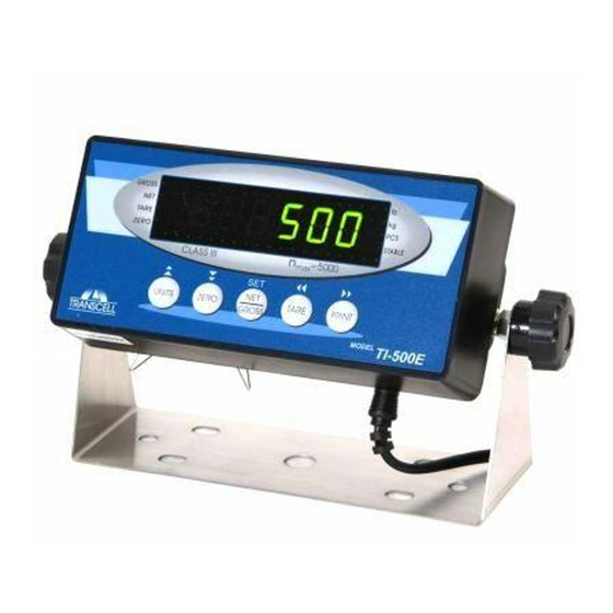
This light is on whenever the scale is stable. Indicates that the indicator is displaying peak weight Flashes when the battery voltage is too low for normal operation. Replace the batteries. TABLE 4: TI-500 Plus Annunciator Definitions KEYBOARD The keyboard is composed of five function keys shown below. -
Page 16: Function Keys
FUNCTION KEYS Off – This key switches off the indicator. Units – This key toggles the indicator among the available weight units if enabled in the User (“A”) menu. Available weight units include lb, kg and pieces.. Zero - This key sets the indicator to display zero provided the following conditions are met: 1. -
Page 17: Peak Hold Mode
1. If the items you will be counting require a container, you must first tare the container off by pressing the TARE key. NOTE: The TARE key is inoperative when in sampling mode. 2. Press the UNITS key until “5 0” is indicated on the display. If the screen does not show “5 0”, press the ZERO key once. -
Page 18: Appendix A: Specifications
Keyboard 6-key flat membrane panel POWER TI-500 Plus (Battery) 4-AA alkaline (1.5 V) or rechargeable (1.2 V) TI-500 Plus (AC Adapter) 6 VDC, 100mA Female TI-500SS Plus 100-240 VAC, 50/60 Hz, 30W DC Power Consumption 20mA + 15mA/350 Load Cell... -
Page 19: Appendix B: Serial Port Information
APPENDIX B: SERIAL PORT INFORMATION SERIAL PORT MODES DEMAND DUPLEX MODE The Demand Duplex Mode provides a two way serial transmission mode In this mode, the output information is transmitted on demand; either by pressing the PRINT key on the indicator’s front panel or upon receiving a recognized command from a host device (i.e. -
Page 20: Output Strings
OUTPUT STRINGS TEXT PRINT TICKET The Text Print Ticket is designed specifically for a serial printer. ID. NO. 123456 GROSS 25.00 LB TARE 1.48 LB 23.52 LB NOTES: 1. The TARE and NET fields are not printed unless a tare has been established in the system. -
Page 21: Appendix C: Displayed Error Codes
APPENDIX C: DISPLAYED ERROR CODES CODE MODE MEANING / POSSIBLE SOLUTION Normal Operating Gross Overload. A weight greater than the rated capacity has been Mode applied to the scale. Remove the weight from the platter or try re- calibrating the scale. Otherwise, check for a bad load cell connection or possible load cell damage due to overloading. - Page 22 TI-500E Plus Digital Weight Indicator Setup / Operation Manual Revision 1.2 September 16, 2011...
- Page 23 TABLE OF CONTENTS Page INTRODUCTION ..............................1 FCC NOTE ................................1 INSTALLATION ..............................2 PREPARATION ..............................2 CONNECTIONS ..............................2 CONNECTING THE WEIGH PLATFORM ....................... 3 CONNECTING THE SERIAL I/O DEVICE ....................3 CONNECTING THE POWER SUPPLY ......................3 CONFIGURATION .............................. 4 OVERVIEW ..............................
-
Page 24: Transcell Technology, Inc. 2008. All Rights Reserved
©Transcell Technology, Inc. 2008-2011. All rights reserved. The information contained herein is the property of Transcell Technology and is supplied without liability for errors or omissions. No part may be reproduced or used except as authorized by contract or other written permission. The copyright and the foregoing restriction on reproduction and use extend to all media in which the information may be embodied. -
Page 25: Installation
INSTALLATION PREPARATION Any precision instrument requires a suitable environment in which to operate as intended. Please review each of the following prior to installation: Electrical Power The TI-500E Plus indicator has been designed to operate from 9 to 12 VDC and ships with an AC adapter designed to operate from the local line voltage. -
Page 26: Connecting The Weigh Platform
CONNECTING THE WEIGH PLATFORM The TI-500E Plus ships with a 15 ft shielded load cell cable for connection to weigh platform’s load cell(s) or junction box. 1. Plug the cable’s 14-pin parallel interface connector into the load cell port on the rear panel of the indicator. -
Page 27: Configuration
CONFIGURATION OVERVIEW The indicator contains two main configuration menus: • The Setup (“F”) menu, which configures the indicator to your weigh platform • The User (“A”) menu, which configures the serial communication port and enables some user options The Setup and User menus consist of several menu selections, each with its own sub-menu of selections or programming procedures. -
Page 28: Setup Menu Descriptions
To move to a new heading, use the TARE (left) or PRINT (right) key to move right or left in the Menu. To move to the selection or programming level, press the ZERO (down) key once. The currently saved selection is shown. To view the available selections for the current heading, use the TARE (left) or PRINT (right) key to move through the selection field. - Page 29 CODE/NAME DESCRIPTION SELECTION LIST Selects the primary base unit to be used in the calibration process. 1 (NA) Also the default unit for normal operation. Calib. Unit 2 (€) "1" = primary unit is lb. "2" = primary unit is in kg. Determines the desired weight increments.
-
Page 30: Setup Menu Procedures
CODE/NAME DESCRIPTION SELECTION LIST Selects the range within which the scale will automatically clear the Key-in tare and switch to Gross mode. Note that the scale must be in 0 - 10 Gross Zero standstill. Selections are in display divisions (d). Scrolling down with Band 0 (NA) the ZERO key one level begins the procedure. -
Page 31: User Menu Descriptions
USER MENU DESCRIPTIONS This section provides more detailed descriptions of the selections found in the User Menu Chart. Factory-set defaults are shown in bold; (NA) for North America and ( ) for Europe. € CODE/NAME DESCRIPTION SELECTION LIST Selects the baud rate for data transmission through the serial port. 300, 600, 1200, 2400, 4800, Baud Rate... -
Page 32: User Menu Procedures
USER MENU PROCEDURES This section provides instructions for all of the User Menu procedures. ID Number Entry (A8) 1. While in the User Menu mode, scroll to "A 8", and then scroll down once using the ZERO key to enter the ID Number menu. 2. -
Page 33: Calibration
CALIBRATION CALIBRATION OVERVIEW If your indicator was shipped as a complete scale, then calibration is not necessary. Please check with your installer or supplier if you are unsure. Transcell recommends having your weighing equipment checked by a qualified scale technician at least once a year depending on its intended use and working environment. -
Page 34: View Calibration Values (F18)
6. At this time it is suggested that the calibration values be recorded for future use (see next section). If the calibration was not successful, one of the error messages below will appear. Take the indicated action to correct the problem, and then perform a new calibration. "Err0"... -
Page 35: Key-In Zero Calibration Value (F19)
KEY-IN ZERO CALIBRATION VALUE (F19) Note: This procedure is intended for emergency use only in the case of non-volatile memory loss. A valid zero calibration value, obtained from a successful F16 calibration procedure, must be used. 1. While in the Setup mode, scroll to "F 19", and then scroll down once using the ZERO key. The display will momentarily show "ET C 0", followed by a value of zero 2. -
Page 36: Operation
OPERATION DISPLAY This model utilizes a 6-digit LED (Light Emitting Diode) display. Table 4 summarizes the display annunciators. GROSS TARE ZERO STABLE MEANING Annunciator Better known as the “Center of Zero” annunciator, this light is active ZERO whenever the displayed weight is within a pre-programmed band from true zero. -
Page 37: Keyboard
KEYBOARD The keyboard is composed of five function keys shown below. ZERO TARE PRINT UNITS GROSS FUNCTION KEYS Units – This key toggles the indicator among the available weight units if enabled in the User (“A”) menu. Available weight units include lb, kg and pieces. Zero - This key sets the indicator to display zero provided the following conditions are met: 1. -
Page 38: Piece Counting Mode
PIECE COUNTING MODE IMPORTANT NOTE: The piece counting function cannot be used in commercial (NTEP) applications. To activate this mode, set F30 to 3. This mode is used to indicate the number of pieces of an item you have placed on the scale’s platform and is accessed by pressing the UNITS key. To ensure accuracy, the parts you are counting must be consistent in weight. -
Page 39: Remote Display Mode
REMOTE DISPLAY MODE To activate this mode, set F30 to 2. This mode is used to emulate a remote display for a separate indicator. For it to work properly, a remote indicator must be transmitting information to the TI-500E Plus continuously and at the same transmission (baud) rate configured in A1. LEGAL FOR TRADE SEALING Indicators can be sealed for commercial (Legal for Trade) applications as follows. -
Page 40: Appendix A: Specifications
APPENDIX A: SPECIFICATIONS ANALOG SPECIFICATIONS Full Scale Input Signal ±3.125 mV/V 0.3 µV / grad Minimum Sensitivity - Non trade 0.6 µV / grad Minimum Sensitivity - H-44/R76 Input Impedance 30MΩ, typical Internal Resolution Approximately 260,000 counts @ 2mV/V input Display Resolution 50,000 display division max Measurement Rate... -
Page 41: Appendix B: Serial Port Information
APPENDIX B: SERIAL PORT INFORMATION SERIAL PORT MODES DEMAND DUPLEX MODE The Demand Duplex Mode provides a two way serial transmission mode. In this mode, the output information is transmitted on demand; either by pressing the PRINT key on the indicator’s front panel or upon receiving a recognized command from a host device (i.e. -
Page 42: Output Strings
OUTPUT STRINGS TEXT PRINT TICKET The Text Print Ticket is designed specifically for a serial printer. ID. NO. 123456 GROSS 25.00 LB TARE 1.48 LB 23.52 LB NOTES: 1. The TARE and NET fields are not printed unless a tare has been established in the system. -
Page 43: Appendix C: Displayed Error Codes
APPENDIX C: DISPLAYED ERROR CODES CODE MODE MEANING / POSSIBLE SOLUTION Normal Operating Gross Overload. A weight greater than the rated capacity has been Mode applied to the scale. Remove the weight from the platter or try re- calibrating the scale. Otherwise, check for a bad load cell connection or possible load cell damage due to overloading. - Page 44 Digital Weight Indicator Setup / Operation Manual Revision 1.1 April 6, 2009...
- Page 45 ©Transcell Technology, Inc. 2009. All rights reserved. The information contained herein is the property of Transcell Technology and is supplied without liability for errors or omissions. No part may be reproduced or used except as authorized by contract or other written permission. The copyright and the foregoing restriction on reproduction and use extend to all media in which the information may be embodied.
-
Page 46: Introduction
INTRODUCTION The TI-500 Digital Indicator is a general purpose, industrial grade weight indicator. One model is currently available, characterized by display type, enclosure type and power supply. Table 1 shows the TI-500 product details. This model can readout up to 50,000 display divisions and can supply enough current for up to 4-350 load cells. -
Page 47: Installation
INSTALLATION PREPARATION Any precision instrument requires a suitable environment in which to operate as intended. Please review each of the following prior to installation: Electrical Power The TI-500 indicators have been designed to operate from 4-AA alkaline/rechargeable batteries and ships with an AC adapter designed to operate from the local line voltage. The unit ships with the appropriate power plug for its area of intended use. -
Page 48: Connecting The Weigh Platform
CONNECTING THE WEIGH PLATFORM The TI-500 ships with a 15 ft shielded load cell cable for connection to weigh platform’s load cell(s) or junction box. 1. Plug the cable’s 14-pin parallel interface connector into the load cell port on the rear panel of the indicator. -
Page 49: Configuration
CONFIGURATION OVERVIEW The indicator contains two main configuration menus: The Setup (“F”) menu, which configures the indicator to your weigh platform The User (“A”) menu, which configures the serial communication port and enables some user options The Setup and User menus consist of several menu selections, each with its own sub-menu of selections or programming procedures. -
Page 50: Setup Menu Descriptions
MENU STRUCTURE All menus consist of a top level (heading) and a secondary level. The top level contains the code (e.g. F1) for the parameter to be configured. The secondary level contains the selection list or allows access to a programming sequence. - Page 51 CODE/NAME DESCRIPTION SELECTION LIST Selects the range (expressed as a percentage of full scale capacity) 100% within which the scale may be zeroed. Note that the indicator must be Zero Range 1.9% in standstill to zero the scale. Sets the level at which motion is detected. If motion is not detected, the scale can process a Print or Zero command.
- Page 52 USER MENU DESCRIPTIONS This section provides more detailed descriptions of the selections found in the User Menu Chart. Factory-set defaults are shown in bold with a checkmark ( ). CODE/NAME DESCRIPTION SELECTION LIST Selects the baud rate for data transmission through the serial port. 1200 2400 Baud Rate...
-
Page 53: User Menu Procedures
CODE/NAME DESCRIPTION SELECTION LIST Tells MP-20 printer to print the header information. Valid only when Print Header A6 is set to “1”. "0" = Do NOT Print Header "1" = Print Header Selects the auto off time period in minutes: Auto Power Off “Off”... -
Page 54: Calibration
CALIBRATION CALIBRATION OVERVIEW If your indicator was shipped as a complete scale, then calibration is not necessary. Please check with your installer or supplier if you are unsure. Transcell recommends having your weighing equipment checked by a qualified scale technician at least once a year depending on its intended use and working environment. -
Page 55: View Calibration Values (F18)
If the calibration was not successful, one of the error messages below will appear. Take the indicated action to correct the problem, and then perform a new calibration. "Err0" - The calibration test weight or the keyed-in weight is larger than the full capacity of the scale. -
Page 56: Display
OPERATION DISPLAY This model utilizes a 6-digit LCD (Liquid Crystal Display). Table 3 summarizes the display annunciators. MEANING Annunciator Better known as the “Center of Zero” annunciator, this light is active whenever the displayed weight is within ± 0.25 divisions of true zero. Indicates that the indicator is displaying net weight. -
Page 57: Function Keys
KEYBOARD The keyboard is composed of five function keys shown below. FUNCTION KEYS Off – This key switches off the indicator. Units – This key toggles the indicator among the available weight units if enabled in the User (“A”) menu. Available weight units include lb and kg. Zero - This key sets the indicator to display zero provided the following conditions are met: 1. -
Page 58: Legal For Trade Sealing
LEGAL FOR TRADE SEALING Indicators can be sealed for commercial (Legal for Trade) applications as follows. Category I Audit Trail: Configuration and calibration audit counters update each time a configuration or calibration change occurs. These counters will return to zero after 1000 changes, individually. The counters may be viewed by powering up the unit: - The screen will display the configuration audit counter ("CF") and the calibration audit counter ("CA"). -
Page 59: Appendix B: Serial Port Information
APPENDIX B: SERIAL PORT INFORMATION SERIAL PORT MODES DEMAND DUPLEX MODE The Demand Duplex Mode (A3 = ‘d’, A6 = ‘0’) provides a two way serial transmission mode In this mode, the output information is transmitted on demand; either by pressing the PRINT key on the indicator’s front panel or upon receiving a recognized command from a host device (i.e. -
Page 60: Output Strings
OUTPUT STRINGS TEXT PRINT TICKET The Text Print Ticket is designed specifically for a serial printer. ID. NO. 123456 GROSS 25.00 lb TARE 1.48 lb 23.52 lb NOTES: 1. The TARE and NET fields are not printed unless a tare has been established in the system. -
Page 61: Appendix C: Displayed Error Codes
APPENDIX C: DISPLAYED ERROR CODES CODE MODE MEANING / POSSIBLE SOLUTION Normal Operating Gross Overload. A weight greater than the rated capacity has been applied Mode to the scale. Remove the weight from the platter or try re-calibrating the scale. Otherwise, check for a bad load cell connection or possible load cell damage due to overloading. - Page 62 TI-500E Digital Weight Indicator Setup / Operation Manual Revision 3.0 July 6, 2012...
- Page 63 TABLE OF CONTENTS Page INTRODUCTION ..............................2 FCC NOTE ................................2 INSTALLATION ..............................3 PREPARATION ..............................3 CONNECTIONS ..............................3 CONNECTING THE WEIGH PLATFORM ....................... 4 CONNECTING THE SERIAL I/O DEVICE ....................4 CONNECTING THE POWER SUPPLY ......................4 CONFIGURATION .............................. 5 OVERVIEW ..............................
-
Page 64: Introduction
©Transcell Technology, Inc. 2009-2012. All rights reserved. The information contained herein is the property of Transcell Technology and is supplied without liability for errors or omissions. No part may be reproduced or used except as authorized by contract or other written permission. The copyright and the foregoing restriction on reproduction and use extend to all media in which the information may be embodied. -
Page 65: Installation
INSTALLATION PREPARATION Any precision instrument requires a suitable environment in which to operate as intended. Please review each of the following prior to installation: Electrical Power The TI-500E indicator has been designed to operate from 9 to 12 VDC and ships with an AC adapter designed to operate from the local line voltage. -
Page 66: Connecting The Weigh Platform
CONNECTING THE WEIGH PLATFORM The TI-500E ships with a premium 15 ft shielded load cell cable for connection to weigh platform’s load cell(s) or junction box. 1. Plug the cable’s 14-pin parallel interface connector into the load cell port on the rear panel of the indicator. -
Page 67: Configuration
CONFIGURATION OVERVIEW The indicator contains two main configuration menus: • The Setup (“F”) menu, which configures the indicator to your weigh platform • The User (“A”) menu, which configures the serial communication port and enables some user options The Setup and User menus consist of several menu selections, each with its own sub-menu of selections or programming procedures. -
Page 68: Menu Structure
MENU STRUCTURE All menus consist of a top level (heading) and a secondary level. The top level contains the code (e.g. F1) for the parameter to be configured. The secondary level contains the selection list or allows access to a programming sequence. Use the directional keys to move around in the Menu Structure shown below. - Page 69 CODE/NAME DESCRIPTION SELECTION LIST 1d√ √ √ √ Sets the level at which motion is detected. If motion is not detected, the scale can process a Print or Zero command. Maximum value Motion Band varies depending on local regulations. Expressed as scale divisions per second (d/s).
-
Page 70: User Menu Descriptions
USER MENU DESCRIPTIONS This section provides more detailed descriptions of the selections found in the User Menu Chart. Factory-set defaults are shown in bold with a checkmark. NAME/CODE DESCRIPTION CODE/VALUE Selects the baud rate for data transmission through the serial port. 1200 2400 9600√... -
Page 71: User Menu Procedures
USER MENU PROCEDURES This section provides instructions for all of the User Menu procedures. ID Number Entry (A8) 1. While in the User Menu mode, scroll to "A 8", and then scroll down once using the ZERO key to enter the ID Number menu. 2. -
Page 72: Calibration
CALIBRATION CALIBRATION OVERVIEW If your indicator was shipped as a complete scale, then calibration is not necessary. Please check with your installer or supplier if you are unsure. Transcell recommends having your weighing equipment checked by a qualified scale technician at least once a year depending on its intended use and working environment. -
Page 73: View Calibration Values (F18)
If the calibration was not successful, one of the error messages below will appear. Take the indicated action to correct the problem, and then perform a new calibration. "Err0" - The calibration test weight or the keyed-in weight is larger than the full capacity of the scale. - Page 74 4. If the entered values are entered successfully, the display will show "E CAL 1" momentarily before reverting back up to F20.
-
Page 75: Operation
OPERATION DISPLAY This model utilizes a 6-digit LED (Light Emitting Diode) display. Table 3 summarizes the display annunciators. MEANING Annunciator Better known as the “Center of Zero” annunciator, this light is active ZERO whenever the displayed weight is within a pre-programmed band from true zero. -
Page 76: Keyboard
KEYBOARD The keyboard is composed of five function keys shown below. ZERO TARE PRINT UNITS GROSS FUNCTION KEYS Units – This key toggles the indicator among the available weight units if enabled in the User (“A”) menu. Available weight units include lb, kg and pieces. Zero - This key sets the indicator to display zero provided the following conditions are met: 1. -
Page 77: Piece Counting Mode
PIECE COUNTING MODE IMPORTANT NOTE: The piece counting function cannot be used in commercial (NTEP) applications. To activate this mode, set F24 to 1. This mode is used to indicate the number of pieces of an item you have placed on the scale’s platform and is accessed by pressing the UNITS key. To ensure accuracy, the parts you are counting must be consistent in weight. -
Page 78: Legal For Trade Sealing
LEGAL FOR TRADE SEALING This indicator can be sealed for commercial (Legal for Trade) applications as follows. 1. Power off the indicator. 2. On the back of the indicator, locate the setup/calibration switch cover. 3. Thread a wire security seal through both drilled head screws securing the calibration switch cover as well as the single drilled head screw holding on the rear panel. - Page 79 APPENDIX A: SPECIFICATIONS ANALOG SPECIFICATIONS Full Scale Input Signal ±3.125 mV/V 0.3 µ V / grad Minimum Sensitivity - Non trade 0.6 µ V / grad Minimum Sensitivity - H-44 30M Ω , typical Input Impedance Internal Resolution Approximately 200,000 counts @ 3mV/V input Display Resolution 50,000 display divisions max Measurement Rate...
-
Page 80: Appendix B: Serial Port Information
APPENDIX B: SERIAL PORT INFORMATION SERIAL PORT MODES DEMAND DUPLEX MODE The Demand Duplex Mode (A3 = ‘d’, A6 = ‘0’) provides a two way serial transmission mode. In this mode, the output information is transmitted on demand; either by pressing the PRINT key on the indicator’s front panel or upon receiving a recognized command from a host device (i.e. -
Page 81: Output Strings
OUTPUT STRINGS TEXT PRINT TICKET The Text Print Ticket is designed specifically for a serial printer. Ensure that A3 is set to ‘d’ and A6 is set to ‘1’ or ‘2’. The A6=2 setting is reserved for operators who are using a Transcell MP-20 printer with labels and desire to have the labels feed automatically after each printout. -
Page 82: String Format 2 (Condec Continuous String)
STRING FORMAT 2 (Condec Continuous String) String Format 2 is designed for one-way communication. Ensure that A3 is set to ‘C’ and A6 is set to ‘0’. <STX> <POL> xxxxx.xx <L/K> <G/N> <STAT> <CR> <LF> Gross/Net: Start Weight Data Carriage G = Gross Transmission Return...
Need help?
Do you have a question about the TI-500 Plus and is the answer not in the manual?
Questions and answers