Table of Contents
Advertisement
Quick Links
Table of Contents
CPM2 .................................................................................................. 2
DVL2A ................................................................................................. 2
Principal Features ................................................................................ 2
Power and Supervision ........................................................................ 2
Compatibility ....................................................................................... 2
CPM2 Outputs ..................................................................................... 2
1.1 Receiver Setup and Operation without Programming .................. 3
3.1 Mounting the Receiver ................................................................. 4
3.2 Printer Connections ...................................................................... 4
3.3 Computer Connections ................................................................ 4
3.4 Grounding .................................................................................... 4
3.5 Power Supply ............................................................................... 4
3.6 Battery Charging Current ............................................................. 4
3.7 Removing and Installing System Components ............................. 5
MLR2-DV Installation Maximum Configuration ..................................... 5
DML4 Connections .............................................................................. 6
DML2A Backplane Connections to RS-232 ......................................... 6
MLR2-DV Backplane Connection Diagram .......................................... 7
Connections for DML2A Line Card Expansion .................................... 7
4.1 Switches and LEDs on the SG-DVL2A ......................................... 8
5.1 DVL2A in Standby Mode .............................................................. 9
5.2 Shutdown of Line Card Communication with CPM2 ..................... 9
5.3 CPM2 Error; Display Alarm Messages ......................................... 9
5.4 Keep Last Alarm Message ........................................................... 9
5.5 Standby Mode ............................................................................. 9
5.6 Data Reception ............................................................................ 9
6.1 Line Card Menu Mode ............................................................... 10
6.2 Display Printer Alarm Buffer ....................................................... 10
6.3 Display Caller ID Alarm Buffer ................................................... 10
6.4 Display Computer Alarm Buffer ................................................. 10
6.5 Display System Configuration Buffer .......................................... 10
6.6 Display Program Version ............................................................ 10
6.7 Adjust LCD Contrast .................................................................. 10
Entering Commands .......................................................................... 11
Entering Data .................................................................................... 11
Verifying Data .................................................................................... 11
Option [00]: Common Event Code and Library Selection .......... 12
Option [01]: Communication Select ........................................... 12
Through CPM2 ....................................................... 12
Option [03]: Receiver Number ................................................... 12
Option [04]: Line Card Number .................................................. 12
Option [05]: Caller Identification (Call Display) Option .............. 12
Computer ............................................................... 12
Option [07]: Send Caller Identification to Printer ........................ 12
Option [08]: Mute Buzzer ........................................................... 12
Option [09]: Last Message On ................................................... 12
Option [0A]: Equivalent Line ....................................................... 12
Option [0B]: DSR (min) ............................................................... 13
Option [0C]: CrHEARTBEAT ....................................................... 13
Option [0D]: RAD Output ............................................................ 13
7.2 Buffer Output Command: LC-FA-XX-XX ..................................... 13
LC-FA-01-XX .................................................................... 13
LC-FA-02-XX .................................................................... 13
7.2.3 Output Line Card Configuration: LC-FA-04-04 ................. 13
2
7.3 Shutdown Line Card Communication with CPM2:l LC-FB .......... 14
7.4 Reactivate Line Card Command: LC-FC .................................... 14
7.5 Line Card Buffer Command: LC-FE-XX-XX ................................. 14
3
3
8.1 General Information ................................................................... 15
4
8.2 Features ..................................................................................... 15
8.3 CPM2 Controls ........................................................................... 15
8.4 CPM2 Operating Mode .............................................................. 16
8.4.1 CPM2 Cold Start-up ......................................................... 16
8.5 CPM2 in Standby Mode ............................................................. 16
8.6 CPM2 Configuration Mode ......................................................... 16
8.7 Configuration Options ................................................................ 16
Option 01: Setting the Clock ...................................................... 16
Option 02: Changing System Passwords ................................... 16
Option 03: Change the Number of Line Cards ........................... 17
Option 04: Select Printer Function .............................................. 17
Option 05: COM1 Configuration ................................................. 17
Option 06: COM1 Communication Format ................................. 17
Option 07: Wait Time for Acknowledge on COM1 ...................... 17
8
Option 08: Heartbeat Time for COM1 ........................................ 17
Option 09: COM2 Configuration ................................................. 18
Option 10: COM2 Communication Format ................................. 18
9
Option 11: Adjust LCD Contrast ................................................. 18
Option 12: UL Receiver Option .................................................. 18
Option 13: Erase Alarm Message Buffer .................................... 18
Option 14: Mute Buzzer ............................................................. 18
Option 15: Display Last Message .............................................. 19
Option 16: ComPort Diagnostics ................................................ 19
Option 17: Test 9V/12V Battery .................................................. 19
Option 18: Line Card Diagnostics .............................................. 19
10
Option 19: Display Software Version .......................................... 19
Option 20: Battery Monitor ......................................................... 19
Option 21: Alarm Messages Print Year or Seconds ................... 19
Option 22: System Reset ........................................................... 20
Option 23: Change Receiver Number ........................................ 20
8.8 Message Priorities ...................................................................... 20
8.9 CPM2 Utility Modes .................................................................... 21
[A] Send Computer Messages to Printer .................................... 21
[B] Operator Log-On .................................................................. 21
11
[C] System Command Mode ...................................................... 21
[D] Send Printer Messages to the Printer ................................... 21
[E] Examine Printer Messages on Display Screen ..................... 21
[F] Examine Computer Messages on Display Screen ................ 22
8.10 MLR2-DV Computer Interface .................................................... 22
Section 9: Communication Protocol with
9.1 Protocols .................................................................................... 23
9.1.1 Data Byte Protocol ........................................................... 23
9.1.2 Acknowledgement of the Signal ....................................... 23
9.1.3 DVL2A Communication Formats ...................................... 23
9.1.4 Supervisory Heartbeat Signal Protocol ............................. 23
9.1.5 Clock Signal Protocol ....................................................... 23
9.2 CPM2 EPROM Programming ..................................................... 24
firealarmresources.com
Messages to the Printer: LC-FA-05-XX ............................. 13
LC-FA-06-XX .................................................................... 14
Configuration: LC-FE-04-04 .............................................. 14
15
23
25
27
28
Inside Back Cover
Inside Back Cover
Advertisement
Table of Contents

Subscribe to Our Youtube Channel
Related Manuals for DSC SG SECURITY MLR2-DV


Summary of Contents for DSC SG SECURITY MLR2-DV
-
Page 1: Table Of Contents
Table of Contents 7.2.4 Output Caller Identification and Corresponding Alarm Introduction Messages to the Printer: LC-FA-05-XX ......13 CPM2 ....................2 7.2.5 Output Computer Alarm Messages to the Computer: DVL2A ....................2 LC-FA-06-XX ..............14 Principal Features ................2 7.3 Shutdown Line Card Communication with CPM2:l LC-FB ..14 Power and Supervision ................ -
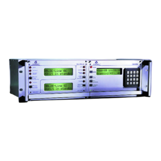
Page 2: Introduction
Introduction The MLR2-DV unit consists of a CPM2 Central Processor 5. Built-in watchdog timer continually monitors line card Module and a DVL2A Receiver Line Card Module. Additional microprocessor operation. DVL2A Line Cards may be added to enable the CPM2 to 6. -
Page 3: Section 1: Quick Start
Section 1: Quick Start Section 2: SG-DVL2A Cold Boot and Changing the Line Card Number 1.1 Receiver Setup and Operation NOTE: Each time you change (update) the Program without Programming Version, by replacing the Program EPROM, the “COLD BOOT” operation should be performed. Otherwise, the Unpacking operating system will not work properly. -
Page 4: Section 3: Installation
Section 3: Installation 3.1 Mounting the Receiver 3.2 Printer Connections • Install the MLR2-DV in a closed 19" rack or cabinet with The following printers can be used with MLR2-DV (ULC a locking rear access door. Cover all unused spaces Listed): with blank metal plates. -
Page 5: Removing And Installing System Components
Section 3 3.7 Removing and Installing System Remove the 4 retaining screws on the front panel of the module. Slowly pull the module out of the metal cabinet. Components After the CPM2 is replaced, remove the temporary battery Note that the receiver does not have to be powered down so that the CPM2 can properly maintain the main battery. -
Page 6: Dml4 Connections
Section 3 AC IN power input HNDSET A Not used AC OUT filtered power output Fused 12V output BATT 12V battery Not Used B.LGT Backlight Power Terminal: connect as Not Used secondary 12V power supply to illuminate Acknowledge Output: this 12V output the LCD screens follows the “Acknowledge”... -
Page 7: Mlr2-Dv Backplane Connection Diagram
Section 3 MLR2-DV Backplane Connection Diagram Connections for DML2A Line Card Expansion firealarmresources.com... -
Page 8: Section 4: Sg-Dvl2A Compatible Line Card
Section 4: SG-DVL2A Compatible Line Card 4.1 Switches and LEDs on the SG-DVL2A Each module of SG-DVL2A has 2 line cards. The LEDs and push button switches on the left side and the upper LCD are for line card #1. The LEDs and push button switches on the right side and the lower LCD are for line card #2. -L01-Digital Rec *Unit in Standby -L02-Digital Rec... -
Page 9: Section 5: Sg-Dvl2A Operating Mode
Section 5: SG-DVL2A Operating Mode 5.1 DVL2A Standby Mode If alarm messages cannot be sent to the CPM2 because of the error, the DVL2A will display the oldest message which With the Line Card installed, apply power to the unit. This has not been manually acknowledged. -
Page 10: Section 6: Sg-Dvl2A Programmable Features
Section 6: SG-DVL2A Programmable Features 6.1 Line Card Menu Mode Press the [ACK] button to display the Call-ID message: When the unit is not on line, pressing the [ACK/FUNCTION] L01-123456789 button will display the first Function Menu: Dsp PRINTER alm •... -
Page 11: Section 7: Dvl2A Programming Commands
Section 7: DVL2A Programming Commands There are 5 main Programming Commands available on the • Enter the Line Card number. In this example, Line Card DVL2A Line Card Module: 01 will be used. When “01” is keyed in, the number will appear on the display as shown below: •... -
Page 12: F7 Line Card Options Programming: Line Card-F7-Option-Code
Section 7 7.1 F7 Line Card Options Programming: Option [04]: Line Card Number The Line Card Number provides a unique identification code Line Card-F7-Option-Code for each Line Card in the DVL2A module. Since the CPM2 The F7 Options Programming command is used to change can be connected to a total of 14 Line Cards, it is very various operating parameters for the Line Card. -
Page 13: Option [0B]: Dsr (Min)
Section 7 Examples: Note that multiple signals may be generated from a single alarm. Option [0A] = 00; no equivalent line number 123456551515557 will be sent If receiver number is 02, and the line number is 3: the to the computer: 1RRLssss123456sAss03[DC4] printer message will be “L03-1234...”... -
Page 14: Output Computer Alarm Messages To The Computer: Lc-Fa-06-Xx
Section 7 7.5 Line Card Buffer Command: 7.2.5 Output Computer Alarm Messages to the Computer: LC-FA-06-XX LC-FE-XX-XX The LC-FA-06-XX command will send the specified number The FE command is used to access the Line Card buffers. of computer alarm messages to the computer. “XX” should The following functions may be performed: be a hexadecimal number from 01 to FE to indicate a number of events from 1 to 254. -
Page 15: Section 8: Sg-Cpm2 Central Processing Module
Section 8: SG-CPM2 Central Processing Module The CPM2 is the central processing module that monitors • Ability to individually examine each Line Card message the DVL2A Line Cards and forwards the information from • “Cold boot” option allows easy installation of default the Line Cards to the computer and printer. -
Page 16: Cpm2 Operating Mode
Section 8 8.4 CPM2 Operating Mode Press the [Enter] button to display the next menu item, or 8.4.1 CPM2 Cold Start-up press the [Backspace] button to display the previous menu The “cold boot” should be performed to install the default item;... -
Page 17: Option 03: Change The Number Of Line Cards
Section 8 representing the initials of the operator, may be assigned Br: Baud Rate Enter... for baud rate to each Password to help in identifying the operator. When this option is entered, a cursor will appear beneath the first character in the 4-digit Password. Enter a new Password using the 0 through 9 and the A through F keys. -
Page 18: Option 09: Com2 Configuration
Section 8 Press the [ACK] button when the “08: Heartbeat Sel” message When the display contrast is adjusted to the desired level, is displayed; this message will be displayed: press the [Escape] button; when the [Escape] button is pressed, the next Configuration Option will be displayed on Heartbeat Select the screen. -
Page 19: Option 15: Display Last Message
Section 8 When programmed as “0”, the buzzer will sound when an Supervise 12V only alarm is received and cannot be forwarded to COM1. The Supervise both batteries default setting is “0”. Option 18: Line Card Diagnostics NOTE: Option 14 will have no effect on the buzzer if the UL The CPM2 features a diagnostics mode that allows the Receiver Option is enabled. -
Page 20: Option 22: System Reset
Section 8 Second” message is displayed; this message will be displayed: UL Requirement Message When Option [12] is programmed as “01”, the “ACK” button Year/Second:1/0 must be pressed to acknowledge each incoming alarm 0 Change to:X manually and to silence the internal buzzer. Program Option [21] as “1”... -
Page 21: Cpm2 Utility Modes
Section 8 8.9 CPM2 Utility Modes • Op: and Cd: “Op” and “Cd” are used to indicate parameters that may be required within certain commands. For example, When the CPM2 is in the Standby Mode, the following functions when using the F7 Line Card programming command may be accessed by pressing the [A] through [F] keys: “Op”... -
Page 22: [F] Examine Computer Messages On Display Screen
Section 8 [Enter] is pressed, a message similar to this will be displayed: every 30 seconds. If the “heartbeat” transmission determines that the computer is off-line or disconnected, a message L01-1234-05 similar to this will be sent to the printer: Alarm Com#1 Absent!! 09:45-21/09/92 •... -
Page 23: Central Station Computer
Section 9: Communication Protocol with Central Station Computer 9.1 Protocols Basic protocol The Sur-Gard MLR2-DV receiver sends the following protocol 1RRLssssAAAAAAsXssYY[DC4] to report signals to the central station computer via the Where, 1 : Protocol number. RS-232 port. : Receiver number. 9.1.1 Data Byte Protocol : Line number. -
Page 24: Cpm2 Eprom Programming
Section 9 9.2 CPM2 EPROM Programming Most of the CPM2 options can be changed in the RAM accessed by the system’s configuration. However, some less important features are installed in the EPROM. The following features are located in the CPM2 standard EPROM and programmed to the following default settings: ROM Address Default... -
Page 25: Appendix A: Cpm2 Quick Reference Guide (V2.0)
Appendix A: CPM2 Quick Reference Guide (v2.0) CPM2 Utility Modes Press [ACK] when “Ack” light flashes to Acknowledge event • [A] Send Computer Messages to Printer • [B] Operator Log-On • [C] System Command Mode • [D] Send Printer Messages to the Printer •... - Page 26 Appendix A UPS Connection firealarmresources.com...
-
Page 27: Appendix B: Trouble Shooting
Appendix B: Trouble Shooting PROBLEM No communication with the central station computer on COM1. SOLUTION Ensure that the cable connected to COM1 is an RS-232 cable; it should not be a null-modem type. Check the baud rate for COM1 (CPM2 option 05). Check the computer software setup. -
Page 28: Appendix C: Ascii Character Chart
Appendix C: ASCII Character Chart ASCII with library on Corresponding ASCII ASCII with library on Corresponding ASCII printer (Option 30) Character printer (Option 30) Character Space Appendix D Quick Reference for DVL2A CSL-X28 Options Option Number Name Default Value Programmed Value RS232C CD __________________ COM SELECT... -
Page 29: Limited Warranty
LIMITED WARRANTY Sur-Gard Ltd. warrants that for a period of sixty months from the date of purchase, the product shall be free of defects in materials and workmanship under normal use and that in fulfilment of any breach of such warranty, Sur-Gard Ltd. shall, at its option, repair or replace the defective equipment upon return of the equipment to its repair depot. - Page 30 © 1997 Sur-Gard Security Systems Ltd. 401 Magnetic Drive, Unit #24, 29002375 R0 Downsview, Ontario, Canada M3J 3H9 Printed in Canada firealarmresources.com...
- Page 31 Installation Manual MLR2-DV Version CSL-X28 1.0 firealarmresources.com...
Need help?
Do you have a question about the SG SECURITY MLR2-DV and is the answer not in the manual?
Questions and answers