Sign In
Upload
Manuals
Brands
DSC Manuals
Security Sensors
SG SECURITY MLR2-DV
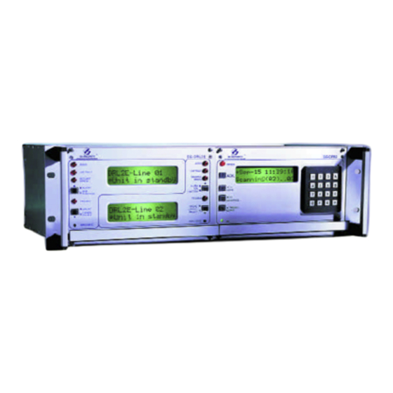
User Manuals: DSC SG SECURITY MLR2-DV Alarm Receiver
Manuals and User Guides for DSC SG SECURITY MLR2-DV Alarm Receiver. We have
1
DSC SG SECURITY MLR2-DV Alarm Receiver manual available for free PDF download: Instruction Manual
DSC SG SECURITY MLR2-DV Instruction Manual (31 pages)
Brand:
DSC
| Category:
Security Sensors
| Size: 1 MB
Table of Contents
Table of Contents
1
Introduction
2
Cpm2
2
Dvl2A
2
Principal Features
2
Power and Supervision
2
Compatibility
2
CPM2 Outputs
2
Section 1: Quick Start
3
Receiver Setup and Operation Without Programming
3
Section 2: SG-DVL2A Cold Boot and Changing the Line Card Number
3
Section 3: Installation
4
Mounting the Receiver
4
Printer Connections
4
Computer Connections
4
Grounding
4
Power Supply
4
Battery Charging Current
4
Removing and Installing System Components
5
MLR2-DV Installation Maximum Configuration
5
DML4 Connections
6
DML2A Backplane Connections to RS-232
6
MLR2-DV Backplane Connection Diagram
7
Connections for DML2A Line Card Expansion
7
Section 4: SG-DVL2A Compatible Line Card
8
Switches and Leds on the SG-DVL2A
8
Section 5: SG-DVL2A Operating Mode
9
DVL2A in Standby Mode
9
Shutdown of Line Card Communication with CPM2
9
CPM2 Error; Display Alarm Messages
9
Keep Last Alarm Message
9
Standby Mode
9
Data Reception
9
Section 6: SG-DVL2A Programmable Features
10
Line Card Menu Mode
10
Display Printer Alarm Buffer
10
Display Caller ID Alarm Buffer
10
Display Computer Alarm Buffer
10
Display System Configuration Buffer
10
Display Program Version
10
Adjust LCD Contrast
10
Section 7: DVL2A Programming Commands
11
Entering Commands
11
Entering Data
11
Verifying Data
11
F7 Line Card Options Programming: Line Card-F7-Option-Code
12
Option [00]: Common Event Code and Library Selection
12
Option [01]: Communication Select
12
Option [02]: Printer Enable: Communicate Information to Printer
12
Through CPM2
12
Option [03]: Receiver Number
12
Option [04]: Line Card Number
12
Option [05]: Caller Identification (Call Display) Option
12
Option [06]: Send Caller-Identification (Telephone Number) to
12
Computer
12
Option [0B]: DSR (Min)
13
Option [0C]: Crheartbeat
13
Option [0D] RAD Output
13
Buffer Output Command: LC-FA-XX-XX
13
Output Alarm Type Printer Messages to the Printer: LC-FA-01-XX
13
Output Alarm Type Computer Messages to the Printer: LC-FA-02-XX
13
Output Line Card Configuration: LC-FA-04-04
13
Output Caller Identification and Corresponding Alarm Messages to the Printer: LC-FA-05-XX
13
Output Computer Alarm Messages to the Computer: LC-FA-06-XX
14
Shutdown Line Card Communication with Cpm2:L LC-FB
14
Reactivate Line Card Command: LC-FC
14
Line Card Buffer Command: LC-FE-XX-XX
14
Erase Alarm Printer/Computer Messages: LC-FE-00-00
14
Backup Current Line Card Configuration: LC-FE-03-03
14
Install Backup Configuration as Current Line Card
14
Configuration: LC-FE-04-04
14
Section 8: SG-CPM2 Central Processing Module
15
General Information
15
Features
15
CPM2 Controls
15
CPM2 Operating Mode
16
CPM2 Cold Start-Up
16
CPM2 in Standby Mode
16
CPM2 Configuration Mode
16
Configuration Options
16
Option 01: Setting the Clock
16
Option 02: Changing System Passwords
16
Option 03: Change the Number of Line Cards
17
Option 04: Select Printer Function
17
Option 05: COM1 Configuration
17
Option 06: COM1 Communication Format
17
Option 07: Wait Time for Acknowledge on COM1
17
Option 08: Heartbeat Time for COM1
17
Option 09: COM2 Configuration
18
Option 10: COM2 Communication Format
18
Option 11: Adjust LCD Contrast
18
Option 12: UL Receiver Option
18
Option 13: Erase Alarm Message Buffer
18
Option 14: Mute Buzzer
18
Option 15: Display Last Message
19
Option 16: Comport Diagnostics
19
Option 17: Test 9V/12V Battery
19
Option 18: Line Card Diagnostics
19
Option 19: Display Software Version
19
Option 20: Battery Monitor
19
Option 21: Alarm Messages Print Year or Seconds
19
Option 22: System Reset
20
Option 23: Change Receiver Number
20
Message Priorities
20
CPM2 Utility Modes
21
[A] Send Computer Messages to Printer
21
[B] Operator Log-On
21
[C] System Command Mode
21
[D] Send Printer Messages to the Printer
21
[E] Examine Printer Messages on Display Screen
21
[F] Examine Computer Messages on Display Screen
22
MLR2-DV Computer Interface
22
Central Station Computer
23
Protocols
23
Data Byte Protocol
23
Acknowledgement of the Signal
23
DVL2A Communication Formats
23
Supervisory Heartbeat Signal Protocol
23
Clock Signal Protocol
23
CPM2 EPROM Programming
24
Appendix A: CPM2 Quick Reference Guide (V2.0)
25
Appendix B: Trouble Shooting
27
Appendix C: ASCII Character Chart
28
Appendix D Quick Reference for DVL2A CSL-X28 Options
28
Limited Warranty
29
How to Contact Us
29
Advertisement
Advertisement
Related Products
DSC MAXSYS PC4020
DSC Mounting Plate HS-MP Series
DSC Maxsys PC4020 - V3.3
DSC Categories
Security System
Security Sensors
Keypad
Control Panel
Cell Phone
More DSC Manuals
Login
Sign In
OR
Sign in with Facebook
Sign in with Google
Upload manual
Upload from disk
Upload from URL