weintek iR-ETN40R Series Installation Instruction
Hide thumbs
Also See for iR-ETN40R Series:
- User manual (60 pages) ,
- User manual (26 pages) ,
- User manual (62 pages)
Advertisement
Quick Links
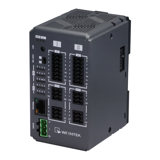
iR-ETN40R series
1
Installation and Startup Guide
This document covers the installation of iR-ETN40R, for the detailed specifications and operation,
please refer to Datasheet, Brochure and Remote I/O User Manual. Please read all warnings,
precautions, and instructions on the device carefully before use.
Install Environment:
The
product has been tested to conform to European CE requirements. This
Electrical
means that the circuitry is designed to resist the effects of electrical noise. This
does not guarantee noise immunity in severe cases. Proper wire routing and
Environment
grounding will insure proper operation.
(1) Make sure that the units are installed correctly and that the operating limits
are followed.
(2) Avoid installing units in environments where severe mechanical vibration or
shocks are present.
Environmental
(3) Do not operate the unit in areas subject to explosion hazards due to
flammable gases, vapors or dusts, or where acid gas, such as SO2 exists.
Considerations
(4) This device should be mounted in the vertical position and for use on the flat
surface enclosure.
(5) For use in Pollution Degree 2 Environment and dry location.
(6) Relative Humidity: 10% ~ 90% (non-condensing)
Unpacking the Unit
2
Unpack and check the delivery. If damage is found, please contact the supplier.
NOTE:
Place the unit on a stable surface during installation. Dropping it or letting it fall may
cause damage.
The package includes:
(1) Installation Instruction, 2-sided A4 *1
(2) iR-ETN40R *1
(3) Power Connector *1
(4) 14pin Terminal *2
(5) 6pin Terminal *4
3
Installation Instructions
Clip assembly: Insert one side of the clip into the hole on the
case. Press down firmly in the direction shown in the figure
on the right until hearing the clip snap
into the case.
Clip removal: Insert a flathead
screwdriver into the gap on the clip
and then lift up the screwdriver.
Placing a finger on the clip when
lifting the screwdriver can prevent the
clip from jumping away. The clip can
also be removed directly by hand.
Installation Instruction
Rail mounting: DIN rail 35mm.
Panel mounting: Use two M4 or #8 panhead screws, mounting hole size is 4.6mm
Plan for adequate space around the unit and inside the enclosure, for ventilation and cables. Consider
the heat from other devices inside the enclosure. The ambient temperature around the unit must be
-10 ~ 60℃
NOTE: Please do not touch any of the connectors when the unit is powered up and running.
4
Power Connections
Power Connector Specifications:
Wire AWG: 28~12
Wire Strip Length: 7~8 mm
Connect positive DC line to the '+'
NOTE:
terminal and the DC ground to the '-' terminal.
I/O Terminal Specifications:
Wire AWG: 24~16
Wiring Example
Communication Connections
5
Please use a CAT.5 (or higher) Ethernet cable.
Advertisement

Related Manuals for weintek iR-ETN40R Series


Summary of Contents for weintek iR-ETN40R Series
- Page 1 Rail mounting: DIN rail 35mm. Panel mounting: Use two M4 or #8 panhead screws, mounting hole size is 4.6mm Plan for adequate space around the unit and inside the enclosure, for ventilation and cables. Consider the heat from other devices inside the enclosure. The ambient temperature around the unit must be -10 ~ 60℃...
- Page 2 This product is limited warranted against defects in design and manufacture. Item Description Default The proven defective product will either be repaired or replaced, at Weintek’s discretion. IP Address 192.168.0.212 This warranty shall not cover any product which is Netmask 255.255.255.0...
Need help?
Do you have a question about the iR-ETN40R Series and is the answer not in the manual?
Questions and answers