weintek iR-ETN40R User Manual
Hide thumbs
Also See for iR-ETN40R:
- Installation instruction (2 pages) ,
- User manual (26 pages) ,
- User manual (62 pages)

Related Manuals for weintek iR-ETN40R


Summary of Contents for weintek iR-ETN40R
- Page 1 User Manual iR-ETN40R User Manual This guide walks through important information about iR-ETN40R UM021002E_20220307...
-
Page 2: Table Of Contents
Table of Contents Product Overview ....................1 Specifications ......................2 LED Indicators ......................4 IO RUN/ERR LED ..................... 4 ENET RUN/ERR ....................4 RJ45 ........................ 4 Reset Button ......................5 I/O Display Switch ....................5 IP Address Setup ..................... 5 MODBUS Mapping .................... - Page 3 Modbus Mapping ....................35 iBus Information Register ................35 Digital Input Bit Mapping to Modbus ............35 Digital Output Bit Mapping to Modbus ............36 Analog Input Mapping to Modbus ............... 36 Analog Output Mapping to Modbus ............36 Module Register Mapping to Modbus ............36 iR-PU01-P Variable Instance Mapping ............
- Page 4 13. Description File ..................... 52 13.1 Weintek HMI Tag ..................52 13.2 EtherNet/IP EDS ................... 52 13.3 CODESYS PLCopen.XML ................52 14. iR-ETN40R IO Wiring ..................... 54 15. iR-ETN40R Firmware Update ................55 15.1 Software ....................... 55 15.2 Firmware Update ..................56 15.3...
-
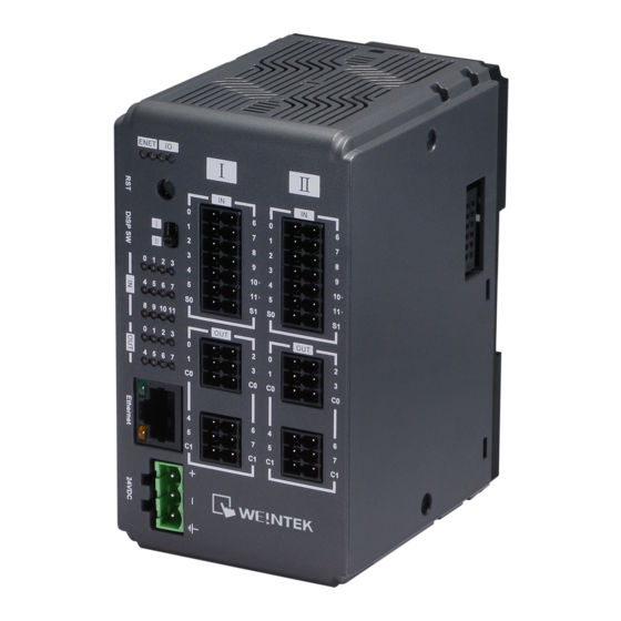
Page 5: Product Overview
User Manual 1. Product Overview Input Terminal b.c.e.f Output Terminal Reset Button I/O Display Switch Ethernet Port Power Connector Expansion Connector... -
Page 6: Specifications
User Manual 2. Specifications Communication Interface Specifications No. of Ports Data Transfer Rate 10/100 Mbps Data Transfer Medium 4 x 2 twisted pair copper cable; category 3 (10 Mbps), category 5 (100 Mbps) Distance Between 100 m between hub/switch and Bus Coupler or between Bus Coupler and Bus Coupler... - Page 7 User Manual Current Consumption 520mA@5VDC Electrical Isolation Logic to Field Power Isolation: Yes Back-up Fuse ≤ 1.6A Self-recovery PCB Coating Enclosure Plastic Specification Dimensions WxHxD 64 x 109 x 81 mm Weight Approx. 0.27 kg Mount 35mm DIN rail mounting...
-
Page 8: Led Indicators
User Manual 3. LED Indicators 3.1 IO RUN/ERR LED Display Module Status RUN LED ERR LED Description Power off or no expansion module is connected Blinking IO initiating Blinking IO initiation error IO working Blinking IO module alarm IO communication fault... -
Page 9: Reset Button
255.255.255.0 5. I/O Display Switch The I/O on iR-ETN40R are split into two Terminals: TerminalⅠand TerminalⅡ. When the I/O Display Switch is flipped upward, the indicators show the states of I/O in TerminalⅠ, and when the switch is flipped downward, the indicators show the states of I/O in TerminalⅡ. -
Page 10: Modbus Mapping
User Manual 7. MODBUS Mapping 7.1 Bit Mapping Start address Parameter Read/Write Function Code 0000~ Digital Input 0~511 Read 01FF Read 0000~ Digital Output 0~511 01FF Write 5,15 7.2 Register Mapping Start address Parameter Read/Write Function Code 0000~ Analog Input... -
Page 11: Device Information Register
User Manual 7.4 Device Information Register Address Read/Write Data size Description 4word 3000 0BB8 Read Vendor name string 8 char: “weintek” (ASCII) 1word 3004 0BBC Read Product Code of iR-ETN40R: 0x0A73 Read 1word 3005 0BBD Firmware revision V1.23.4, 0x1234... -
Page 12: Module Register
User Manual 30039 7557 Read 1word Number of points of Digital Input 30040 7558 Read 1word Number of Analog input channels of module 30041 7559 Read 1word Number of Analog output channels of module 7.7 Module Register Each module is configured with different parameters; please see the corresponding manual of the module used. -
Page 13: Life Guarding Register
User Manual 5002 138A Read 1word Slot1~16 of Module disconnected Setting the time filter (digital input, unit: ms). The time filter is disabled when it is set to less than 5ms. Read/Write 512word 5100~ 13EC~ The time filter remains at 1000ms when it is set to... -
Page 14: Device Error Code List
User Manual 6165- 1815- Read/Write 4word Analog Output Error Mode 0xFF 6168 1818 6169- 1819~ Read/Write 64word Analog Output Error Value 6232 1858 *After pressing [Reset] button, the Default Value will be filled into the corresponding registers. 7.12 Device Error Code List... -
Page 15: Ir-Pu01-P Nmt Control Address
7.16 Pulse Capture Feature iR-ETN40R provides a pulse capture feature which can be used for the local digital inputs. This feature can be used to capture high-going pulses or low-going pulses that are of such a short duration that they would not always be seen when the controller... -
Page 16: High-Speed Input Function
6301 189D Read/Write digital inputs 16~23 in TerminalⅡ. 1:Enable *This feature is only supported for the local digital inputs of IR-ETN40R. 7.17 High-speed Input Function 7.17.1 Function block iR-ETN40R offers 4 high-speed inputs (Input Points 10, 11 of TerminalⅠand Input Points 10, 11 of Terminal Ⅱ). -
Page 17: Register List
User Manual Start/Stop Digital Output Limit &Reset Bidirectional Counter 0-1 High Select Speed Rate Measurement Counter Input Simple Counter 0-3 Digital Output Limit 7.17.2 Register List The maximum input frequency for a counter is 20 KHz. When the input points are configured for A/B phase (Quadrature 4X) encoder use, the maximum input frequency is 10 KHz. - Page 18 User Manual Output ON-trigger Value 4086~4087 OFF -trigger Value 4094~4095 Counter Value 4004~4005 Counter State 4010 Counter Command 4014 Simple Upper Limit Value 4024~4025 Counter-2 Point 4082 Digital ON-trigger Value 4088~4089 Output OFF -trigger Value 4096~4097 Counter Value 4006~4007...
- Page 19 User Manual Upper Limit Reload Value 4060~4061 Lower Limit 4056~4057 Lower Limit Reload Value 4064~4065 Point 4240 ON-trigger Value 4241~4242 OFF-trigger Value 4243~4244 Point 4245 ON-trigger Value 4246~4247 OFF-trigger Value 4248~4249 Point 4250 ON-trigger Value 4251~4252 OFF-trigger Value 4253~4254...
-
Page 20: Input Configuration
User Manual 7.17.3 Input configuration TerminalⅠ SC-0 Point10 Simple Counter-0 Bidirectional Counter -0 Point11 Simple Counter-1 Start/Stop Reset TerminalⅡ SC-0 Point10 Simple Counter-2 Bidirectional Counter -1 Point11 Simple Counter-3 Reset Start/Stop... - Page 21 User Manual TerminalⅠinput (Address: 4044) TerminalⅡinput (Address: 4045) Signal Type points 10 points 11 points 10 points 11 Simple Simple Counter-0 Simple Counter-1 Simple Counter-2 Simple Counter-3 Bidirectional Bidirectional Bidirectional Bidirectional A/B Phase Counter-0 Counter-0 Counter-1 Counter-1 A Phase...
-
Page 22: Rate Measurement
User Manual Single pulse only Simple Counter-0 Simple Counter-1 A/B Phase Quadrature 1X A/B Phase A Phase B Phase Quadrature 2X Bidirectional Counter-0 ) Bidirectional Counter-0 ) A/B Phase Quadrature 4X Up Pulse Down Pulse Up & down pulse... -
Page 23: Simple Counter
User Manual Rate Select Measurement Counter Counter Time Windows Address Read/Write Name Value 1~1000, Unit: ms 4028 0FBC Read/Write Time-Windows Default: 0 0: disable 1: Simple Counter 0 2: Simple Counter 1 4029 0FBD Read/Write Windows Channel 3: Simple Counter 2... - Page 24 User Manual Max 4294967295 (FFFF FFFFH) Up Counting Counter Value Counter Value Reset to Zero Simple Counter Register Address Read/Write Name Value 4000~ 0FA0~ Read/Write Simple Counter 0 value 4001 0FA1 4002~ 0FA2~ Read/Write Simple Counter 1 value...
- Page 25 User Manual The digital outputs of iR-ETN40R are numbered from 0 to 15 (built-in), and the digital outputs of modules are numbered 16+. Setting a value greater than the current total number of outputs is ineffective. Address Read/Write Name...
- Page 26 User Manual Example 1: Digital Output Point ON-Trigger Value OFF -Trigger Value 1000 2000 MAX:4294967295 (FFFF FFFFH) Up Counting Count Value OFF-Trigger ON-Trigger Value Value =2000 =1000 Digital Output Point 0 Example 2: ON-Trigger Value OFF-Trigger Value Digital Output Point...
-
Page 27: High Speed Counter
User Manual 7.17.6 High Speed Counter Function Block Counter Digital Input Output*8 Rate Bidirectional Counter Measurement Counter Start/Stop Counter Reset Lower Limit Upper Limit Lower Upper Limit Reload Value Reload Value Limit Upper Count Limit Lower Count Limit 2,147,483,647 2,147,483,648... - Page 28 User Manual 4052~ 0FD4~ Bidirectional ounter-1 default: 2,147,483,647 Read/Write 4053 0FD5 Upper Limit 4054~ 0FD6~ Bidirectional ounter-0 Read/Write 32bit signed 4055 0FD7 Lower Limit Range:-2,147,483,648~2,147,483,647 4056~ 0FD8~ Bidirectional ounter-1 default:-2,147,483,648 Read/Write 4057 0FD9 Lower Limit 0FDA~ Bidirectional ounter-0 4058~...
- Page 29 User Manual Upper Limit 2,147,483,64 Up Counting Example 2: Item Value Upper Limit 2,147,483,647 Upper Limit Reload Value -2,147,483,647 Lower Limit -2,147,483,647 Lower Limit Reload Value 2,147,483,647 ...
- Page 30 OFF. The 8 digital outputs can be set as the same output point or different output points. The digital outputs of iR-ETN40R are numbered from 0 to 15 (built-in), and the digital outputs of modules are numbered 16+. Setting a value greater than the current total number of outputs is ineffective.
- Page 31 User Manual Counter Counter Counter Counter Value =1000 Value =2000 Value =3000 Value =4000 Digital Output Point Example 2: Number Digital Output Point ON-trigger Value OFF-trigger Value 1000 2000 3000 4000 1000 3000 Counter Counter Counter Counter Value =1000...
- Page 32 User Manual Digital Output: Bidirectional Counter 0 Address Numb Read/Write Name Value 4200 1068 Read/Write Digital Output Point 0 Default: 65535 4201~ 1069~ Digital Output Point 0 Read/Write 32-bit Signed 4202 106A ON-trigger Value Range: 4203~ 106B~ Digital Output Point 0...
- Page 33 User Manual Digital Output: Bidirectional Counter 1 Address Read/Write Name Value Number 4240 1090 Read/Write Digital Output Point 0 Default: 65535 4241~ 1091~ Digital Output Point 0 Read/Write 32-bit Signed 4242 1092 ON-trigger Value Range: 4243~ 1093~ Digital Output Point 0...
-
Page 34: Application Examples
To implement flow control with iR-ETN40R, we make use of the high speed input/counter and a special feature of iR-ETN40R which sets digital outputs ON/OFF upon high-speed counters detecting a certain number of pulses. -
Page 35: Speed Control
When the saw blade passes through the log, its speed slows down. The sensor detects the deceleration, and the conveyer belt is switched to slow speed. Pulses are generated as the saw blade passes through the log, and the pulse speed is computed by iR-ETN40R. Architecture... -
Page 36: Length Measurement
-2 on to start the saw blade and the conveyer belt. The sensor detects the speed of the saw blade and outputs signal to iR-ETN40R. When the saw blade passes through the log, its speed slows down, and the conveyer belt is switched to slow speed (Output -0 = TRUE). - Page 37 In this example, of the four high-speed input channels of iR-ETN40R, we would connect two to the encoder. For the other two, we would connect both to the sensor output and designate one as counter Run/Stop and the other one as counter Reset in the program.
- Page 38 User Manual Parameters Address Name Value (Dec.) Ⅰ When set to 3, the high-speed inputs -10/11 are TerminalⅠHigh Speed Input Setting 4044 configured for A/B phase encoder use. When set to 7, the high-speed inputs -10/11 are TerminalⅡHigh Speed Input Setting...
-
Page 39: Modbus Mapping
User Manual 8. Modbus Mapping The following is an example showing that when connecting with multiple modules, the address mapping and input/output bit mapping are as follows: item Product Slot#1 iR-DI16-K Slot#2 iR-DQ16-P Slot#3 iR-DM16-P Slot#4 iR-DQ08-R Slot#5 iR-AI04-VI... -
Page 40: Digital Output Bit Mapping To Modbus
User Manual Slot#2 iR-DQ16-P Slot#3 iR-DM16-P 0030h~0037h (Input points 0~7) Slot#4 iR-DQ08-R 8.3 Digital Output Bit Mapping to Modbus Bit Offset Function Slot Module Code iR-ETN40R (0000h~0030h) TerminalⅠ: 0000h~0007h Built-in 5,15 TerminalⅡ:0008h~000Fh Slot#1 iR-DI16-K 5,15 Slot#2 iR-DQ16-P 0010h~001Fh (Module output 0~15) -
Page 41: Ir-Pu01-P Variable Instance Mapping
User Manual 8.7 iR-PU01-P Variable Instance Mapping Slot Module Description Address Function Code Slot#7 Axis 0 variable instance input 40000~40015 iR-PU01-P (Axis 0) Axis 0 variable instance output 40500~40515 Slot#8 Axis 1 variable instance input 40016~40031 iR-PU01-P (Axis 1) - Page 42 User Manual 40502 Axis 0 Target Position (Lo word) DINT Signed 32 40503 Axis 0 Target Position (Hi word) 40504 Axis 0 Profile velocity (Lo word) DINT Signed 32 40505 Axis 0 Profile velocity (Hi word) 40506 Axis 0 Target velocity (Lo word)
-
Page 43: Ethernet/Ip Object
User Manual 9. EtherNet/IP Object 9.1 Object List Name Object Type Object Code (Hex) Identity Standard Object Message Router Standard Object Assembly Standard Object Connection Manager Standard Object TCP/IP Interface Standard Object Ethernet Link Standard Object Module Register Manufacturer Defined Object... -
Page 44: Class Attributes & Instance Attributes
User Manual 9.3.1 Class Attributes & Instance Attributes None 9.4 Connection Manager Object Class Code: 06 9.4.1 Class Attributes & Instance Attributes None 9.5 Ethernet Link Object Class Code: F6 9.5.1 Services Service Code Class Instance Name 0x01 ●... -
Page 45: Class Attributes
User Manual 9.6.2 Class Attributes Instance ID Attribute ID Read/Write Name Data Type Value Read Revision UINT Read Max Instance UINT 9.6.3 Instance Attributes Instance ID Attribute ID Read/Write Name Data Type Value Read Interface Status DWORD Read DWORD... -
Page 46: Module Register Object
Data Type Value Slot# Module Read/Write Module Register# Register# The following is an example showing the mapping of Instance ID and Attribute ID when iR-ETN40R is connected to the following modules. Slot Module Name Slot#1 iR-AI04-VI Slot#2 iR-DQ16-P Slot#3 iR-DM16-P... -
Page 47: Ibus Object
User Manual 9.8 iBus Object Class Code: 71 9.8.1 Services Service Code Class Instance Service Name 0x01 ● Set Attribute Single 0x0E ● ● Get Attribute Single 9.8.2 Class Attribute Instance ID Read/Write Name Data Type Value Attribute ID... -
Page 48: Axis Register Object
User Manual Read/Write Analog Output Error UINT Mode (channel 31-16) Read/Write Analog Output Error UINT Mode(channel 47-32) Read/Write Analog Output Error UINT Mode (channel 63-48) 1~64 Read/Write Analog Output Error Value (channel 0-63) 9.9 Axis Register Object Class Code: 80 HEX~ 9.9.1 Services... -
Page 49: High Speed Counter Object
User Manual 9.10 High Speed Counter Object Class Code: 72 9.10.1 Services Service Code Class Instance Service Name 0x01 ● ● Set Attribute Single 0x0E ● ● Get Attribute Single 9.10.2 Instance Attributes Instance ID Attribute ID Read/Write Name... -
Page 50: Ibus Error Handling
DINT Counter0~1 Value 10. iBus Error Handling When communication with the module is lost, iR-ETN40R can report an error and stop module communication. The following actions can be taken: Set Special Register #10045 (273Dh) to 1 to ignore this error. - Page 51 User Manual...
-
Page 52: Power Consumption
User Manual 11. Power Consumption Type Device Consumption(5V) Power Supply(5V) Power Consumption(24V) Coupler iR-ETN40R 520mA/2.6W 2A/10W 255mA/6.12W iR-DM16-P 130mA/0.65W 53mA/1.27W iR-DM16-N 130mA/0.65W 56mA/1.34W iR-DQ08-R 220mA/1.1W 84mA/2.02W Digital I/O iR-DQ16-N 205mA/1.02W 78mA/1.87W iR-DQ16-P 196mA/0.984W 75mA/1.80W iR-DI16-K 83mA/0.418W 31mA/0.74W iR-AQ04-VI 65mA/0.325W 25mA/0.60W... -
Page 53: Easyremoteio
This tool can be found in the installation file of the latest version of EasyBuilder Pro. For more information on EasyRemoteIO, please see EasyRemoteIO User Manual. 1. Preparation: The default domain of iR-ETN40R is 192.168.0.212, please set computer’s IP to 192.168.0.*. 2. Scan iR-ETN40R: Select [Online] »... - Page 54 Select [Online] » [Change IP] to set the iR-ETN40R’s IP address. 4. Check Parameter with Monitor: Select [Online] » [Start Monitoring] or press Shift + M on the keyboard to activate the connection with iR-ETN40R. The device status and module status can be viewed via EasyRemoteIO.
- Page 55 User Manual 5. Export EtherNet/IP EDS file.
-
Page 56: Description File
User Manual 13. Description File When using iR-ETN40R, three types of description files can be generated in EasyRemoteIO. 13.1 Weintek HMI Tag The exported tags can be used for Weintek HMI. For more information about exporting tags, see PLC Connection Guide -> Weintek Remote IO (MODBUS TCP/IP). - Page 57 User Manual 3. After importing the file, the iR-ETN40R added in CODESYS project can be found. Read/Write channels and initial parameters are built.
-
Page 58: Ir-Etn40R Io Wiring
User Manual 14. iR-ETN40R IO Wiring... -
Page 59: Ir-Etn40R Firmware Update
15.1 Software Required software: IO Runtime Updater (ETN) When IO Runtime Updater (ETN) cannot connect to iR-ETN40R’s IP, please check the firewall settings from the directory below: [Windows Defender Firewall] » [Advanced settings] » [Inbound Rules] » [IO Runtime Updater (ETN)] 1. -
Page 60: Firmware Update
2. Wait for the burning process to finish. 15.3 Notes on Updating Firmware Please make sure there is no communication with iR-ETN40R when its firmware is being updated. CODESYS® is a trademark of 3S-Smart Software Solutions GmbH. Other company names, product names, or trademarks in this document are the trademarks or registered trademarks of their respective companies.
Need help?
Do you have a question about the iR-ETN40R and is the answer not in the manual?
Questions and answers