
Related Manuals for weintek iR-PU01-P


Summary of Contents for weintek iR-PU01-P
- Page 1 User Manual iR-PU01-P This guide walks through important information about iR-PU01-P. V1.00...
-
Page 2: Table Of Contents
Table of Contents Product Overview ....................1 Specifications ......................2 Module Specification ..................2 Digital Input Specification ................2 Digital Output Specification ................2 LED Indicators ......................3 AX1 LED ......................3 Run/Error/Warn LED ..................3 I/O LED ......................3 Error Handling ...................... - Page 3 Execution of Function Blocks ............... 34 MC_Power ....................35 MC_MoveVelocity ..................36 MC_Home ....................36 MC_MoveAbsolute ..................37 MC_MoveRelative ..................37 9.10 MC_STOP and MC_Halt ................38 9.11 MC_Reset ..................... 39 9.12 MC_Gear ...................... 40 10. Quick Start of iR-PU01-P in CODESYS CANopen ........... 41...
- Page 4 10.1 Install and Add Weintek Library ..............41 10.2 Launch New Project and Add iR-PU01-P ............41 10.3 Configuring Motion Control Parameters ............42 10.4 Declaration and Programming ..............42 10.5 Axis I/O Mapping..................43 10.6 Login and Run Trial Operation ..............44...
-
Page 5: Product Overview
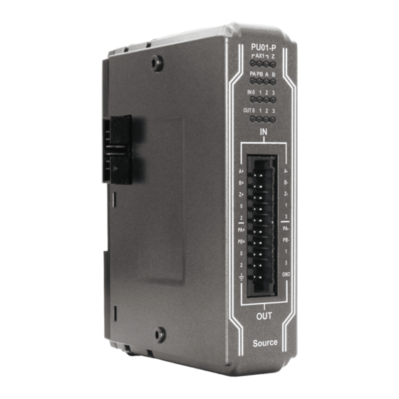
英文版 1. Product Overview Top View 27mm [1.06"] 27mm [1.06"] 81mm [3.19"] iR-DXXX iR-DQ08-R Side View Side View iR-PXXX Front View Bottom View Terminal Expansion Connector... -
Page 6: Specifications
2. Specifications Module Specification Module Name iR-PU01-P Number of Axis 1- Axis PCB Coating Enclosure Plastic Specification Dimensions WxHxD 27 x 109 x 81 mm Weight Approx. 0.12 kg Mount 35mm DIN rail mounting Protection Structure IP20 Storage Temperature -20°... -
Page 7: Led Indicators
3. LED Indicators AX1 LED AX1 Run LED AX1 Error LED AX1 Warm LED Run/Error/Warn LED Run LED Description Axis is not ready Blinking Axis is ready Axis is busy Error LED Description No errors Error occurred Warn LED... -
Page 8: Error Handling
4. Error Handling Function Block Error When using a function block and an error occurs, the diagnostic value is output to the pin in the function block, and ErrorID contains the error code. The following is a list showing how to handle errors. -
Page 9: Error
Motion Error 0 Stop/Reset). 16#6181 Motion Error 1 Changes to an incorrect mode (CiA402) during motion. iR-PU01-P calculates trajectory incorrectly. (Including 16#6182 Motion Error 2 errors caused by Blending.) Incorrect Homing mode or an external signal that is not 16#618A Homing Error configured is used. -
Page 10: Wiring
5. Wiring Notes on Wiring Wiring for Differential Communication Wire length should be minimized (Max: 500m shielded, 300m unshielded). Please use twisted pair cables conform to the impedance matching. If wiring is to be exposed to lightning or surges, use appropriate surge suppression devices. -
Page 11: Differential Output Wiring
Source Digital Input Source Digital Output +24VDC Differential Output Wiring... -
Page 12: Differential Input Wiring
Differential Input Wiring... -
Page 13: Connecting A Coupler
As shown in the following figure, two iR-PU01-P modules are installed respectively on Slot 2 and Slot 4. The iR-PU01-P module installed on Slot 2 uses the first axis (Axis 0), while the iR-PU01-P installed on Slow 4 uses the second axis (Axis 1). -
Page 14: Features
Configurable I/O High Speed Pulse Output iR-PU01-P can output 2MHz pulses to control the connected servo/step motor (velocity and positioning control). Output modes include CW/CCW, Pulse/Direction, Pulse Only, A/B phase * 1、A/B phase * 2、A/B phase * 4. The output mode is configured using Object Dictionary-Index 0x5511 (Axis 0). - Page 15 Pulse/Direction Pulse only A/B Phase...
-
Page 16: High Speed Pulse Input (Encoder)
High Speed Pulse Input (Encoder) iR-PU01-P can receive up to 2MHz pulse input from the signal output by an encoder or Manual Pulse Generator (MPG). Input modes include CW/CCW, Pulse/Direction, Pulse Only, A/B phase * 1、A/B phase * 2、A/B phase * 4. The input mode is configured using Object Dictionary-Index 0x5501 (Axis 0). -
Page 17: Positioning Control (Buffer Mode Supported)
A/B Phase Positioning Control (Buffer Mode Supported) Weintek provides a library of motion control function blocks, and the function blocks relating to positioning control include: MC_MoveAbsolute and MC_MoveRelative, which can perform absolute/relative positioning for the specified target position or for the specified travel distance from current position. -
Page 18: Velocity Control
Buffered Buffered BlendingPrevious BlendingPrevious Velocity Control Weintek provides MC_MoveVelocity function block for controlling the speed of the motor. The module allows V-bias initial speed specification, which makes the motor rotate at specified velocity immediately regardless of acceleration/deceleration rate... -
Page 19: Homing
Each track corresponds to one iR-PU01-P output point. Users can add multiple switches (16 in maximum) to a track, with each switch specifies different position and direction, in order to plan the distance and time output by a point. -
Page 20: Capture
Each iR-PU01-P has five Capture channels for capturing the current axis position value or the timer value of iR-PU01-P, on the rising or falling edge of the input signal. The change of position or time interval can be observed by comparing two captured values (two values captured by one channel, or compared to the latest value from other channels). -
Page 21: Object Dictionary
8. Object Dictionary Data Type Lower Limit Upper Limit Memory SINT -128 8bit USINT 8bit -32768 32767 16bit UINT 65535 16bit DINT -2147483648 2147483647 32bit UDINT 4294967295 32bit Manufacturer Specific Profile Area (5500h - 58FFh) Item Index Range Axis 0(1... - Page 22 In the following list, n=0~3 which represents Axis 0~3. Index Sub Index Description Type ro/rw Default Digital Input 5500h+n*100h DI byte 0 ---- USINT 5501h+ n*100h Pulse Input Method USINT 5502h+ n*100h Input Polarity UDINT Digital Input Function DI 0 Function...
- Page 23 DO 1 Option USINT DO 2 Option USINT DO 3 Option USINT DO A Option USINT DO B Option USINT PWM output setting 551Ah+n*100h PWM Output D0 setting UDINT PWM Output D1/PB setting UDINT Axis Settings0 5520h+n*100h Motion Cycle Time...
-
Page 24: Digital Input:5500H
Track PB Source USINT DigitalCamSwitch (m=0~15) MC_CAMSWITCH_REF 6*m+1 Switch m TrackNumber USINT 6*m+2 Switch m FirstOnPosition DINT 5583h+n*100h 6*m+3 Switch m LastOnPosition DINT 6*m+4 Switch m AxisDirection USINT 6*m+5 Switch m CamSwitchMode USINT 6*m+6 Switch m Duration(ms) UINT Motion Output Settings... -
Page 25: Pulse Input Method:5501H
Bit7 Bit6 Bit5 Bit4 Bit3 Bit2 Bit1 Bit0 Reserved DI-3 DI-2 DI-1 DI -0 Value 0: Input state is OFF Value 1: Input state is ON 8.1.2 Pulse Input Method:5501h Sub Index 00h: Pulse Input Method Bit7- Bit 5 :Reserved... -
Page 26: Input Polarity:5502H
A(*4) B(*4) 8.1.3 Input Polarity:5502h Sub Index 00h: Input Polarity Bit7 Bit6 Bit5 Bit4 Bit3 Bit2 Bit1 Bit0 Reserved DI-3 DI-2 DI-1 DI -0 Value 0: non-reverse Value 1: reverse 8.1.4 Digital Input Function:5503h Digital Input Functions Sub Index... -
Page 27: Digital Output:5510H
Rejected when input pulse duration is less than or equals to pulse duration threshold. 8.1.6 Digital Output:5510h Sub Index 01h: Input Settings Bit7 Bit6 Bit5 Bit4 Bit3 Bit2 Bit1 Bit0 Reserved DO-3 DO-2 DO-1 DO -0 Sub Index 02h: Output State... -
Page 28: Output Polarity:5512H
Pulse Direction A(*2) B(*2) A(*4) B(*4) 8.1.8 Output Polarity:5512h Sub Index 00h: Output Polarity (not effective to pulse output) Bit7-Bit6 Bit5 Bit4 Bit3 Bit2 Bit1 Bit0 Reserved DI-3 DI-2 DI-1 DI -0 Value 0: non-reverse Value 1: reverse 8.1.9 Digital Output Function:5513h... -
Page 29: Pwm Output Setting:551Ah
DO 2 2:Keep last value Effective when output function is set to Normal, DO 3 PWM will be Off , and Axis Pulse will Quick Stop 8.1.11 PWM Output Setting:551Ah Sub Index Description Name Output D0 setting D0 D1 period less than 10(100k) is counted as 10. -
Page 30: Axis Setting0:5520H
8.1.12 Axis Setting0:5520h Sub Index Name Motion Cycle Time Bias Velocity 8.1.13 Axis Setting1:5521h Sub Index Name Description Backlash compensation (pulse) Range: 0~65535 8.1.14 Additional position modulo range:5528h Sub Index Name Description 1st additional position modulo range Value 0: Linear(Finite) Axis... -
Page 31: Digitalcamswitch Track Position Valuesource:5581H
Bit4:Input A Bit3:Input DI-3 Bit2:Input DI-2 Bit1:Input DI-1 Bit0:Input DI-0 0:Track Disable 1:Track Enable 8.1.18 DigitalCamSwitch Track Position ValueSource:5581h Sub Index Name Description Track D0 ValueSource Track D1 ValueSource Track D2 ValueSource 0:Cmd Position(1st additional) Track D3 ValueSource 1:Act Position(2nd) -
Page 32: Capture Enable:5590H
Reserved bit5 bit4 bit3 DO 3 0:Disable bit2 DO 2 1:Enable bit1 DO 1 bit0 DO 0 8.1.21 Capture Enable:5590h Sub Index Name Description bit31-bit6 Reserved bit5 Channel 5 bit4 Channel 4 Capture Enable Byte 0 bit3 Channel 3... -
Page 33: Capture Status:5598H
Capture Setting Channel 4 Capture Setting Name Value bit 31-20 Reserved bit 16~19 Interval 0~4 Interval between channel0~4 0 : OFF bit 15 Interval Mode 1: On bit 14 Reserved 0 : OFF bit 13 Continuous Mode 1: On... -
Page 34: Standardized Device Profile Area (6000H - 7Fffh)
Standardized device profile Area (6000h - 7FFFh) Item Index Range Axis 0(1 6000-67FF* Axis 1(2 6800-6FFF Axis 2(3 7000-77FF Axis 3(4 7800-7FFF Axis 0’s Object will be in the same index range 6000-67FF as AIO and DIO. Please see Cia402’s document for more information on Object Dictionary. - Page 35 Gear ratio UDINT 6091h+n*800h Motor shaft revolutions UDINT Driving shaft revolutions Feed constant UDINT 6092h+n*800h Feed UDINT Shaft revolutions 6098h+n*800h Homing method SINT Homing speeds UDINT 6099h+n*800h Speed during search for switch 1000 UDINT Speed during search for zero...
-
Page 36: Motion Control Function Blocks
UDINT 67FFh+n*800h Device type FFFF0192h 9. Motion Control Function Blocks Weintek Motion Control Function Blocks designed according to PLCopen Motion Control makes it easy to give motion control instructions to iR-PU01-P. Motion Control Function Block List Item Name Description AXIS_REF_LITE Information on the corresponding axis. -
Page 37: Mc_Status
Step 3. Motion Function Blocks are ready for use now. MC_Status The PLCopen motion standard provides a way to have standard application libraries that are reusable for multiple hardware platforms, which reduces costs during development, maintenance and training. The states of axes and state transitions... -
Page 38: Execution Of Function Blocks
The operation of an axis when motion control instructions are executed for it is shown in the following figure, and the arrows show state transitions. When any error occurs, the state changes to Errorstop. ※Status in the red frame in the following figure is the initial state. -
Page 39: Mc_Power
Enable: When Enable variable is ON, execution of function block continues, and the execution stops when Enable if OFF. Modifications to the parameters during execution are usually effective. Busy, Active, Done, In***, CommandAbort, and Error are output variables that indicate the execution status of function blocks. -
Page 40: Mc_Movevelocity
MC_MoveVelocity MC_MoveVolocity function block performs velocity control for the specified axis. The following parameters are used when executing MC_MoveVelocity. Velocity: Specify the target velocity and the rotation direction. Positive velocity = positive direction, negative velocity = negative direction. Acceleration: Specify the acceleration rate, the value cannot be 0. -
Page 41: Mc_Moveabsolute
Standstill state after homing is completed. MC_MoveAbsolute The MC_MoveAbsolute function block moves the axis to a specified absolute target position. The following parameters are used when executing MC_MoveAbsolute. Position: Specify the absolute target position. -
Page 42: Mc_Stop And Mc_Halt
Position: Specify the target position, which equals to current position + specified distance. Velocity: Specify the target velocity, the value cannot be 0. Acceleration/Deceleration: Specify the acceleration / deceleration rate, the value cannot be 0. After executing this function block, the axis enters Discrete Motion state, and returns to Standstill state after positioning is completed. -
Page 43: Mc_Reset
Deceleration: Specify the deceleration rate, the value cannot be 0. The axis enters Standstill state after it stops. 9.11 MC_Reset Triggering MC_Reset function block can reset the errors when the axis turns into Errorstop state due to error. The axis enters Disabled state when MC_Power is FALSE, and the axis enters Standstill state when MC_Power is TRUE. -
Page 44: Mc_Gear
9.12 MC_Gear MC_Gear function block converts the input pulse from MPG (Manual Pulse Generator) into output pulse. Since pulse input and output use different axes (master axis and slave axis), Pulse Input Method 5501h must be configured: Bit 4: 0 (axis encoder), 1 (external encoder), please set Bit 4 to 1 (external encoder) to use MPG. -
Page 45: Quick Start Of Ir-Pu01-P In Codesys Canopen
(PA, PB). Pulse output modes include: A/B phase (*1/*2/*4), CW/CCW, Pulse/Direction, Pulse Only. Please check the input method used by the motor, and configure iR-PU01-P in accordance. Please also take wiring into consideration. The following steps explain how to start iR-PU01-P module. -
Page 46: Configuring Motion Control Parameters
Max. Profile Velocity 16#607F 16#00 200000 Quick Stop Quick Stop 16#6085 16#00 1000000 Deceleration The above parameters should be configured in advance for iR-PU01-P to perform pulse control. 10.4 Declaration and Programming Declare Axis000 and run trial operation of Function Blocks. -
Page 47: Axis I/O Mapping
Use FBD (Function Block Diagram) programming. The following three function blocks are used for JOG operation: MC_Power: Starts motion control system MC_MoveVelocity: Performs velocity control. MC_Stop: Decelerates until stop. 10.5 Axis I/O Mapping Mapping of input variables can be found in Axis000.Mapping_I, and mapping of output variables can be found in Axis000.Mapping_Q, the user only need to fill in the... -
Page 48: Login And Run Trial Operation
Press xPEnable_Power & xServe_ON button to execute MC_Power function block to start iR-PU01-P. Press xJOG_exe button to execute MoveVelocity function block to make iR-PU01-P output pulse for velocity control. Release xJOG_exe to execute MC_Stop function block to decelerate pulse output to a...
Need help?
Do you have a question about the iR-PU01-P and is the answer not in the manual?
Questions and answers