Table of Contents
Advertisement
Quick Links
Advertisement
Table of Contents

Subscribe to Our Youtube Channel
Related Manuals for Carman AUTO-i 100


Summary of Contents for Carman AUTO-i 100
- Page 1 AUTO-i 100 User Manual Ver. 180719 CARMAN IT CO., LTD.
-
Page 2: Table Of Contents
AUTO-i 100 Contents Precautions for Use ........................4 Chapter 1: General 1. Product Feature........................7 2.Product Specification......................8 3. Component List......................9 4. Component Pictures and Description ................11 5. Name and Function of Each Part..................20 6. Power Supply......................22 Chapter 2: Menu Configuration 1. Menu Description......................23 2. - Page 3 AUTO-i 100 Contents Chapter 5: Stored Data 1. Parameter Record......................56 2. Text Shot.......................57 3. Image Shot........................58 4. Print........................59 Chapter 6: Repair Information 1. Repair Information Menu....................60 2. Sorted By Parts......................61 3. Sorted By Troubles....................65 4. Circuit Diagram........................67 5. Parts Description.........................68 6.
-
Page 4: Precautions For Use
Precautions for Use Safety Regulations 1. Precautions for use The AUTO-i 100 described in this guide was manufactured for those who have the basic knowledge required for its use. Users should follow the safety instructions described in this manual for safe and efficient use of the product. - Page 5 When power is not supplied through the vehicle diagnosticconnector,Connect cigar cable for power supply beforecommunicating with the vehicle. If voltage levels are not matchedbetween ECU and AUTO-i 100, it may disable Communication. 2-2. Before using the product, make sure to download the latest diagnostic program.
- Page 6 AUTO-i 100 Precautionsfor Use 3-3. Usage Do not drop the product. It may cause damage to the product. Do not put the product on a distributor. Although manufactured to prevent interference of internal electromagnetic wave, any strong interference beyond the setlimit mayresult in damage to the product.
-
Page 7: Chapter 1: General
▶Maintenance is possible during operation since maintenance informationis provided. ▶As a PC-based device with an unlimited data storage space, it can easilyupdate the diagnostic program through internet. ▶You can change the sound effects and display unit of the AUTO-i 100. ▶Wireless communication provides more convenient vehicle diagnosis. -
Page 8: Product Specification
AUTO-i 100 Chapter 1: General 2. Product Specification Item Specifications Windows XP, Windows VISTA, Windows7 (32bit), Windows8 (32bit), Windows10 (32bit) And Recommended Over 1GHz processor, 1GB RAM, Hard Disc. Space PC specification 16GB, DirectX 9 Graphic (WDDM 1.0 Driver) Bluetooth Connecting Method USB 2.0 (Compliant) -
Page 9: Component List
AUTO-i 100 Chapter 1: General 3. Component List ◈ Basic kit(AUTO-i100) Part No. Description FE-MUDE-0052 USB Memory Stick AY-ELPT-A100 AUTO-i100 Main Module FE-MUDE-0051 Mini Bluetoothdongle CB-CYAU-001A USB Cable(B Type) CB-CYVG-0006 Cigarette Lighter Power Cable CB-CYAU-010A OBD-II Extension Cable 1m PK-BGTT-0007 AUTO-i100 Carrier Bag ◈... - Page 10 AUTO-i 100 Chapter 1: General ◈ Asian kit Part No. Description CB-AYVG-0008 SAMSUNG / NISSAN ADAPTOR (14P) CB-AYHC-0018 KIA ADAPTOR 20P (BLUE) CB-AYVG-0005 DAEWOO,GM ADAPTOR (12P) CB-AYVG-0006 SSANGYONG ADAPTOR (14P) CB-AYVG-0007 SSANGYONG ADAPTOR (20P) CB-AYVG-0001 TOYOTA, LEXUS ADAPTOR (17P"R") CB-AYVG-0002 TOYOTA, LEXUS ADAPTOR (17P"C")
-
Page 11: Component Pictures And Description
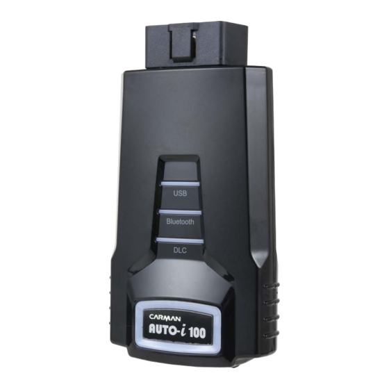
AUTO-i 100 Chapter 1: General 4. Component pictures and description 1-1.USB Memory Stick 1-2. AUTO-i100 Main Module... - Page 12 AUTO-i 100 Chapter 1: General 1-3. Mini Bluetooth Dongle 1-4. USB Cable Be sure to use a dedicated USB cable only. A dedicated USB cable of AUTO-i 100 is not allowed to use for other purpose.
- Page 13 AUTO-i 100 Chapter 1: General 1-5. Cigar Light Power Cable - Cigar Light Power Cable- The Cigar Light Cable connects the AUTO-i 100 to the cigar jack for power supply. 1-6. OBD-II Extension Cable (1m) -OBD-II Extension Cable-...
- Page 14 AUTO-i 100 Chapter 1: General 1-7. Tablet Option - TECLAST T book 10+ - TABLET PC Boots - Tablet Kit – ※ The model and specifications of the tablet PC can be changed without notice.
- Page 15 AUTO-i 100 Chapter 1: General 1-8.DLC ADAPTER The DLC Adapter is used to diagnose vehicles by connecting to the main connector. Do check name of brand written on adapter before use since shape of DLC Adapters are similar. Some products of the same brand include more than one adapter. Therefore do check form and number of pin of the diagnostic connector which is attached to the vehicle.
- Page 16 AUTO-i 100 Chapter 1: General TOYOTA, LEXUS ADAPTOR (17P"R")TOYOTA, LEXUS ADAPTOR (17P"C") HONDA ADAPTOR (3P)HONDA ADAPTOR (5P) SUBARU ADAPTOR (16P-9P)MAZDA "C" ADAPTOR (17P) MAZDA ADAPTOR (6P + 1P)
- Page 17 AUTO-i 100 Chapter 1: General MITSUBISHI CABLE (12P) MITSUBISHI CABLE (12P+16P)
- Page 18 AUTO-i 100 Chapter 1: General 2) European kit MERCEDES BENZ BORAD (38P)MERCEDES BENZ CABLE (3 liners) PSA CABLE(2P) AUDI / VW CABLE(2+2P) FIATCABLE(3P) OPELADAPTOR (10P) BMW ADAPTOR (20P)
- Page 19 AUTO-i 100 Chapter 1: General 3) USA/ Australian kit FORDCABLE(20P) HOLDENCABLE(6P)
-
Page 20: Name And Function Of Each Part
AUTO-i 100 Chapter 1: General 5. Name and function of each part Front View of Main Module 1. DLC LED: Communication with a vehicle 2. Bluetooth LED: Bluetooth communication 3. USB LED: Communication with a USB port 4. PWR LED: External power supply. (12V DC, DLC power supply) - Page 21 AUTO-i 100 Chapter 1: General Upper part of Main Module ○ 1 ○ 2 ○ 3 1. Power connector: It is for a AC/DC power adaptor and a cigar light power cable. 2. USB B TPYE: Connecting to PC for USB communication &update.
-
Page 22: Power Supply
AUTO-i 100 Chapter 1: General 6. Power Supply Power can be supplied through the following 3 ways. 1. Cigarette Lighter Power Cable Power is fed through the cigarette lighter power cable. However, when the vehicle ignition switch is in the “OFF” position or upon starting a vehicle, power is not supplied to the cigarette lighter socket. -
Page 23: Chapter 2: Menu Configuration
AUTO-i 100 Chapter 2: Menu Configuration 1. Menu Description This is the description for each menu displayed on the initial screen when AUTO-i 100is program on. 01. OBD2/EOBD - This menu is to diagnose and test some parts that are related with exhaust gas only if user`s vehicle has OBD 2/EOBD 02. -
Page 24: Icons On Main Screen
Chapter 2: Menu Configuration 2. Icons on Main Screen This is description of each menu displayed on the initial screen when AUTO-i 100 is program on. ○ 1 ○ 2 ○ 3 ○ 4 ○ 5 ○ 6 ○ 7 ○... -
Page 25: How To Connect Diagnostic Connector And Select Diagnosis Program
AUTO-i 100 1. How to Connect Diagnostic Connector and Select Diagnosis Program 1. Locate the diagnostic connector in the vehicle. - Most vehicles released after year 2002 conform to the OBD-II Protocol andhave OBD-II diagnostic connectors. - Most OBD-II vehicles have their diagnostic connectors on the section over the brake pedal under the steering wheel. - Page 26 AUTO-i 100 3.Click on “CAR”. 4. Select the vehicle maker. -Selection of vehicle maker- *RECENT LIST: Save ten latest diagnosed vehicles to simplify same procedures. *GUIDE: Provides “Demo Mode”, “VIN Decoder”, “PIN Code Generator”, Hardware Check” functions. Chapter 3: Vehicle Diagnosis...
- Page 27 AUTO-i 100 5. Select the vehicle name. 6. Select the system. Chapter 3: Vehicle Diagnosis...
- Page 28 AUTO-i 100 7. Click on “OBD-II 16PIN CONNECTOR”. Chapter 3: Vehicle Diagnosis...
-
Page 29: Diagnostic Trouble Codes
- In this menu, it is possible to check for any malfunction of the selected vehicle system through the communication with the ECU in the vehicle. As AUTO-i 100 displays DTCs (Diagnostic Trouble Codes), you can easily check where malfunction occurs. - Page 30 AUTO-i 100 If it does not show a menu like page 31 and shows "Communication Error" or does not communicate stably, please check first status of the target car or connection of cables. 2. The DTC search screen appears. Now, you can check current and old DTCs and erase them.
- Page 31 AUTO-i 100 3. Click current DTC icon to confirm its content. 3-1. DTC - Press this button to check current DTCs. - In the case of MIL type vehicle, you can check codes through the DTC list. 3-2. History DTC - Press this button to check old DTCs.
-
Page 32: Erase/Reset Dtc
AUTO-i 100 3. Erase/Reset DTC 1. If you select a car and a system correctly on the menu and if communication with a car works successfully, it shows the DIAG MENU like a picture below. Press the ERASE/RESET DTC button. -
Page 33: Parameter Data
AUTO-i 100 - In the PARAMETER DATA menu, the module can communicate with the vehicle ECU to check data and control values of each sensor of the selected system and to check conditions of various switches and actuators. It is important to select the vehicle specifications correctly for accurate sensor data measurement. - Page 34 AUTO-i 100 2.The Live data list is displayed as shown in the below picture. - Fix: Select sensor(s) to use Graph Mode and Flight Record Start. (Maximum 32 item-selection available.) - Graph Mode: Converts sensor data to graph for analyzing data stream.
- Page 35 AUTO-i 100 - Graph Mode: This function is to check live data in graph forms for tendencyanalysis. - Stop: More accurate failure analysis is available at any point in time. Select cursor A/B to each value and the time difference between A/B.
- Page 36 AUTO-i 100 - Dual DTC: Displays DTC and its sensor data. Top half screen displays sensor data and bottom half screen displays its DTC. Chapter 3: Vehicle Diagnosis...
- Page 37 AUTO-i 100 Compare based on the reference sensor data (normal vehicle) and the current vehicle sensor data value, the comparison is made using the maximum and minimum values of the reference vehicle. Saving reference sensor data :Save sensor data by existing text shot button...
- Page 38 AUTO-i 100 Comparison of sensor data: When a value outside the reference range, it is displayed in red. ※ The value displayed from the comparison value may be different from the reference value range of actual sensor. Please use for reference only.
-
Page 39: Actuator Test
AUTO-i 100 5. Actuator Test Actuator test is a function to diagnose abnormalities in the applicable product by forcefully operating or stopping actuator and switches. The support of Actuator test function depends on vehicle maker and vehicle type. 1. If a car and a system are selected correctly in the Vehicle Diagnosis menuand communication with vehicle is stable, the above picture will be shown Select a Actuator Test. - Page 40 AUTO-i 100 2.The screen as below appears. 3.When pressing start key icon, Actuator test starts. Before starting inspection, confirm operation conditions and inspect accordingly. Actuator test time varies according to items. Chapter 3: Vehicle Diagnosis 4.When pressing stop key icon, Actuator test stops.Use this key to stop the inspection.
-
Page 41: Resetting Adaptive Values
AUTO-i 100 Inspection stops when pressing ESC key or arrow on the upper right of the screen. Evaluation on Actuator test results is determined by operatingsounds of actuator and switches, and vehicle’s RPM change. Therefore, Actuator test should be conducted in a quiet placewhere surrounding noises are limited. -
Page 42: Evap. Leakage Test
AUTO-i 100 - The resetting adaptive values initiates ECU by clearing values of sets in ECU. - The clearing learning values may be different depend on car makers and models Chapter 3: Vehicle Diagnosis 7. Evap. Leakage Test... -
Page 43: Pcm Lock(Mec) Setting
AUTO-i 100 - Press this button to check if there is leakage from a oil tank. Chapter 3: Vehicle Diagnosis 8. PCM Lock(MEC) Setting - This function is to prevent data or programs from adjustment. -
Page 44: Misfire Delay Reason
AUTO-i 100 - System information differs from depend on car makers and models. Chapter 3: Vehicle Diagnosis 9. Misfire Delay Reason - This function is to check the number of misfire in each cylinders. -
Page 45: System Information
AUTO-i 100 - System information differs from depend on car makers and models. Chapter 3: Vehicle Diagnosis 10. System Information -System Information shows information related with system such as system model and software version etc. -
Page 46: Chapter 4: Obd-Ii/Eobd Diagnosis Menu
AUTO-i 100 - System information differs from depend on car makers and models. Chapter 4: OBD-II/EOBD Diagnosis Menu 1. OBD-II/EOBD Overview ■ Purpose of OBD-II - To diagnose causes of increased exhaust gas from the vehicle and the applicable... -
Page 47: Readiness Test
AUTO-i 100 component and then illuminate a malfunction indicator light(MIL) to notify the need of immediate and accurate repair. ■ OBD-II regulations - If vehicle’s exhaust gas increases due to malfunction of any component, diagnose the applicable component and causes and turn on MIL. -
Page 48: Parameter Data
AUTO-i 100 1. Once it communicates successfully with vehicle, the following menu is displayed. Please click READINESS TEST function. - Readiness Test - If no menu like above is displayed or communication cannot be established, check the vehicle condition and the connections status of the diagnostic connector again. -
Page 49: Diagnostic Trouble Codes
AUTO-i 100 1. Once it communicates successfully with vehicle, click sensor data item as below. - Parameter Data- 2. It displays selected sensor data as below, and you can check each data value - OBD-II/EOBD Sensor Data - Chapter 4: OBD-II/EOBD Diagnosis Menu 4. -
Page 50: Erase/Reset Dtc
AUTO-i 100 1. Once it communicates successfully with vehicle, click DTC item as below. -Diagnostic Trouble codes- 2. It displays DTC as below, and it support DTC erase. - DTC - Chapter 4: OBD-II/EOBD Diagnosis Menu 5.Erase/Reset DTC 1. Select a car model and system in the diagnosis menu. Then, if communication with the... -
Page 51: Monitoring Test Results
AUTO-i 100 vehicle is established successfully, the menu shown in Figure of Page49 appears. Select the ERASE/RESET DTC button. -Erase/Reset DTC- 2. If the “YES” button&“NO”button window are shown, Select the YES button to clear DTC or select the NO button to return back to previous step. - Page 52 AUTO-i 100 component IDs. If there is no test item supported by the vehicle manufacturer, an error message will be displayed. 1. Once it communicates successfully with vehicle, click the item of Monitoring Test Result as below - Monitoring Test Results -...
- Page 53 AUTO-i 100 2. It displays test result of each Monitoring Test item. Chapter 4: OBD-II/EOBD Diagnosis Menu...
-
Page 54: Bi-Directional Control
AUTO-i 100 7.BI-Directional Control - You can control and test functions related with OBD-II system. -BI-Directional Control- 6-1. If communication with the vehicle is established successfully, the menu above appears. Select BI-DIRECTIONAL CONTROL. If no menu like picture above is displayed or communication cannot be established, check the vehicle condition and the connection status of the diagnostic connector again. -
Page 55: Vehicle Information
AUTO-i 100 8. Vehicle Information A function to confirm information on the installed ECU in the vehicle, which is executable only in ECU provided with module information. 1. Once it communicates successfully with vehicle, click vehicle information item as below. -
Page 56: Parameter Record
3. Data View: Views detail information of the selected file on the list. 4. Convert Excel: Converts to type of Excel file. 5. Attach: Attached the selected file to email to the Technical Support Team of Carman IT Co. Ltd. Chapter 5: Stored Data... -
Page 57: Text Shot
AUTO-i 100 2. Text Shot - A function to view and compare the saved DTC and sensor data at specific time point for analyzing 1. Compare: Compares selected two lists. 2. Print: Prints selected file. Chapter 5: Stored Data 3. Image Shot... -
Page 58: Print
AUTO-i 100 - Displays saved image file. 1. Image View- Displays full screen. Chapter 5: Stored Data 4. Print... -
Page 59: Chapter 6: Repair Information
AUTO-i 100 - It prints the Check List or selected file from the saved list through the connected printer. 1. Preview: Previews the prints. 2. Check List: Views and prints Check List. Chapter 6: Repair Information... -
Page 60: Repair Information Menu
AUTO-i 100 1. Repair Information Menu 1.Sorted By Parts Tips are provided for the desired component by 4 systems; engine / engine(LPG) / ABS / suspension system. 2. Sorted By Troubles Tips are provided for desired malfunction type by 4 systems;... -
Page 61: Sorted By Parts
AUTO-i 100 2.Sorted By Parts - Menu by Component Type- Click [Troubles] in menu window on the left. ☞ Tips for malfunction description of selected sensor and repair method. - Troubles - Chapter 6: Repair Information Click [Pictures of parts] in menu window on the left. - Page 62 AUTO-i 100 ☞ Tips for picture of selected sensor Click [Location of Parts] in menu window on the left. ☞ Tips for location of part of selected sensor Chapter 6: Repair Information Click [Part Description] in menu window on the left.
- Page 63 AUTO-i 100 ☞ Tips for detailed principles and function of parts -Part Description– Click [Part Characteristics] in menu window on the left. ☞ Tips for characteristics of selected sensor. -Part Characteristics– Chapter 6: Repair Information Click [Principles Understanding] in menu window on the left.
- Page 64 AUTO-i 100 ☞ Tips for principles of parts. -Principles Understanding - : icon to move to next screen. : icon to move to previous screen. : icon to change the menu window on the left to full screen or basic screen.
-
Page 65: Sorted By Troubles
AUTO-i 100 3.Sorted By Troubles -Menu by Type of Malfunction- Click [Cause of Problem] in menu window on the left. ☞ Tips for cause of malfunction -Cause of Problem - Chapter 6: Repair Information Click [Related Parts] in menu window on the left. - Page 66 AUTO-i 100 ☞ Description of component related to malfunction. -Related Parts– Click [Analysis Method] in menu window on the left. ☞ Tips for analysis method for malfunction symptoms. -Analysis Method– Chapter 6: Repair Information...
-
Page 67: Circuit Diagram
AUTO-i 100 4. Circuit Diagram -Vehicle wiring diagrams menu - If you “drag” the screen, the wiring diagram location changes. -Vehicle wiring diagram– : Screen can be adjusted to condensed / extended / full screen with icons on the top of the screen. -
Page 68: Parts Description
AUTO-i 100 5. Parts Description - Part Description Menu– Click the desired part in menu window on the left. ☞ Tips for parts description - Part Description– Chapter 6: Repair Information... -
Page 69: Parts Location
AUTO-i 100 6. Parts Location - Parts Location Menu – Click the vehicle and model year to be confirmed in menu window on the left. ☞ Location will be confirmed by clicking the name of part in activated window on the right. -
Page 70: Repair Data
AUTO-i 100 7. Repair Data - Maintenance Data Menu – Click the vehicle and system to be confirmed in menu window on the left. ☞ Applied vehicle type, applied specification, function description, execution method, and order of execution will appear in the window on the right. -
Page 71: Web Manual
AUTO-i 100 8. Web Manual -Provides link to each maker’s service information site. Motordata: Please refer to “MOTORDATA INSTALLATION MANUAL” file in your DVD. Chapter 7: Configuration 1. System Configuration... - Page 72 AUTO-i 100 In this menu, you can change the display unit of data which are sent from a vehicle. - The units of various information, such as speed, temperature, pressure, angle, air flow can be checked and modified. 1)It is possible to change the display units all at once according to the region that uses“Metric”...
- Page 73 AUTO-i 100 -System Language: sets operating system language of PC program. 21 languages are available. -Diag. Language: sets diagnostic language. Diagnostic languages can be selected up to the installed diagnostic languages in internal memory. -Screen Size: sets screen size of program.
- Page 74 AUTO-i 100 1. Start ->Settings 2. Devices 3. Select Bluetooth->Select AUTO i-Device Serial Number ->Pair...
- Page 75 AUTO-i 100 4. Input Passcode (0000) ->Next 5. Completed Pairing Pairing setting in AUTO –i Diag Program...
- Page 76 AUTO-i 100 1. Run the AUTO–i Diagprogram 2. Click on “CONFIG” 3. Select the type of the device (AUTO–i100) and connection method (MINIBLUETOOTH)and input the serial number. Then, click on “Save”. 4. Rerun AUTO–i Diag->Completed Pairing...
- Page 77 AUTO-i 100...
-
Page 78: Lock
AUTO-i 100 Chapter 7: Configuration 2.Lock You can set the password. -Enter Password- 2-1 Settinga password The password can be set to a 4-digit number. - Page 79 AUTO-i 100 -Enter Password- Chapter 7: Configuration LOCK setting - LockOn : You can activate the lock function. - Lock Off : A password is deleted. -LOCK screen-...
-
Page 80: Graph Configuration
AUTO-i 100 -Change the password- ※Caution : When you forget your password,please contact to Carman IT. Chapter 7: Configuration 3. Graph Configuration You can set the display environment when confirming current data values with graph. - Graph line, color or thickness of background screen CH1~8: The colors of each channel can be changed. - Page 81 AUTO-i 100 Chapter 7: Configuration 4. System Info. Displays System and License Information. Before your upgrade, be sure to check your current application/diagnostic program information.
-
Page 82: System Information
AUTO-i 100 Chapter 7: Configuration 5. User Info. You can input your information or check system information. 5-1. User information is shown and you can edit and save information. 5-2. In order to change information, please select an item to edit, click the edit button on... -
Page 83: Update
AUTO-i 100 Chapter 8: Update This is the function for updating software and firmware of Auto-i100. 1. Connect Auto-i100 to PC by using a USB cable. 2. Select the update menu after running the diagnostic program. - Page 84 AUTO-i 100 3. Select the checkbox after checking the version and state. 4. Click on “Update”. 5. Chapter 8: Update 6. Click on “OK” after checking the updated equipment.
- Page 85 AUTO-i 100 7. The update file is being downloaded. Chapter 8: Update 8. Click on “OK” to process after finishing downloading.
-
Page 86: Fcc And Ce Certificates
AUTO-i 100 FCC and CE Certificate... - Page 87 AUTO-i 100...
- Page 88 AUTO-i 100...
- Page 89 AUTO-i 100 Copyright The copyright for this guide is reserved to Carman IT Co., Ltd. Use of this guide, either wholly or partially, is prohibited without pre-approval of Carman ITCo., Ltd. Carman IT Co., Ltd 2F, 144, Hyeonchung-ro, Dongjak-gu, Seoul, 06983, Korea Email:sales@carmanit.com...
Need help?
Do you have a question about the AUTO-i 100 and is the answer not in the manual?
Questions and answers