Table of Contents
Advertisement
Quick Links
AUTO-i 700
User Guide
Ver. 180719
Safety Cautions
! This information is essential to protect your safety and prevent property damage.
! Make sure to read this thoroughly before using AUTO-i700.
! This information is subject to change or add without notice.
! Please refer to Homepage of CARMAN IT Co., Ltd. for the latest version.
Grade A Equipment (Communication Equipment for business purpose)
Pay attention that this is electromagnetic compatibility equipment for business purpose (Grade A).
It is permitted to use except a house.
CARMAN IT CO., LTD.
1
Advertisement
Table of Contents

Related Manuals for Carman AUTO-i 700


Summary of Contents for Carman AUTO-i 700
- Page 1 ! Make sure to read this thoroughly before using AUTO-i700. ! This information is subject to change or add without notice. ! Please refer to Homepage of CARMAN IT Co., Ltd. for the latest version. Grade A Equipment (Communication Equipment for business purpose) Pay attention that this is electromagnetic compatibility equipment for business purpose (Grade A).
-
Page 2: Table Of Contents
AUTO-i 700 Table of Contents Cautions in Use..................4 CHAPTER 1General Descriptions...............5 1. Product Features............5 2. Product Specifications............6 3. Rechargeable Battery...........7 4. Component List............8 5. Component Figures and Descriptions............11 6. Power Supply............24 CHAPTER 2Menu Configuration............25 1. Before Getting Started..................25 2. Menu Description..................26 3. - Page 3 AUTO-i 700 Table of Contents CHAPTER 5Diagnosis Menu................42 1. How To Connect Self-Diagnostic Connector and Select Diagnosis Program.........42 CHAPTER 6Vehicle Diagnosis..........45 1. Diagnostic Trouble Codes................45 2. Erase/reset DTC ................48 3. ParameterData................49 4. Actuator Test ..................58 5. Resetting Adaptive Values................61 6. EVAP. Leakage Test ................62 7.
-
Page 4: Cautions In Use
Cautions in use Safety Instruction Cautions in Use AUTO-i 700 mentioned in this User's Guide is designed for those who have basic qualifications for using this system. Users should follow the safety instructions for safe and efficient use of the product. -
Page 5: Chapter 1General Descriptions
▶ You can use saved data and upgrade the diagnosis program by connecting the product to your PC with wire or wireless. ▶ You can change the sound effects and display unit of the AUTO-i 700. ▶Provides the LCD brightness adjustment function. -
Page 6: Product Specifications
Operating Voltage 8V ~ 35V - Please note that if AUTO-i 700 has been under 0℃(32F), it has to stay in room temperature over 2 hours surely before using it over 0℃. -If AUTO-i 700 moves from low temperature to room temperature, condensations inside the device can be generated and it can cause damage or malfunction. -
Page 7: Rechargeable Battery
AUTO-i 700 Chapter 1: General Descriptions 3. Rechargeable Battery * The rechargeable battery pack has the following features -Voltage of the rechargeable battery pack gradually decreases even when the system does not run. - Before using the product for the first time, be sure to fully charge the battery. -
Page 8: Component List
AUTO-i 700 Chapter 1: General Descriptions 4. Component List 1. Basic kit Part No. Description AY-ELPT-A700 AUTO-i 700 Main Body CB-CYAT-0001 DLC Main Cable (16P 2M) CB-CYVG-0006 Cigarette Lighter Power Cable CB-CNHC-0004 Battery Extension Cable PC-02HC-P009 Power adapter (5A) CB-CYTP-0004... - Page 9 AUTO-i 700 Chapter 1: General Descriptions 5. Cable Component 1) Asian kit Part No. Description CB-AYVG-0008 SAMSUNG / NISSAN ADAPTOR (14P) CB-AYHC-0018 KIA ADAPTOR 20P (BLUE) CB-AYVG-0005 DAEWOO,GM ADAPTOR (12P) CB-AYVG-0006 SSANGYONG ADAPTOR (14P) CB-AYVG-0007 SSANGYONG ADAPTOR (20P) CB-AYVG-0001 TOYOTA, LEXUS ADAPTOR (17P"R") CB-AYVG-0002 TOYOTA, LEXUS ADAPTOR (17P"C")
- Page 10 AUTO-i 700 Chapter 1: General Descriptions 2) European kit Part No. Description CA-PSA1-0002 Peugeot / Citroen Cable (2P) CB-CYHC-0022 Audi / VW Cable (2+2P) CN-T005-AM06 Fiat Cable (3P) CB-AYVG-0014 Opel Adapter (10P) CB-AYVG-0013 BMW Adapter (20P) 3) USA/Australian kit Part No.
-
Page 11: Component Figures And Descriptions
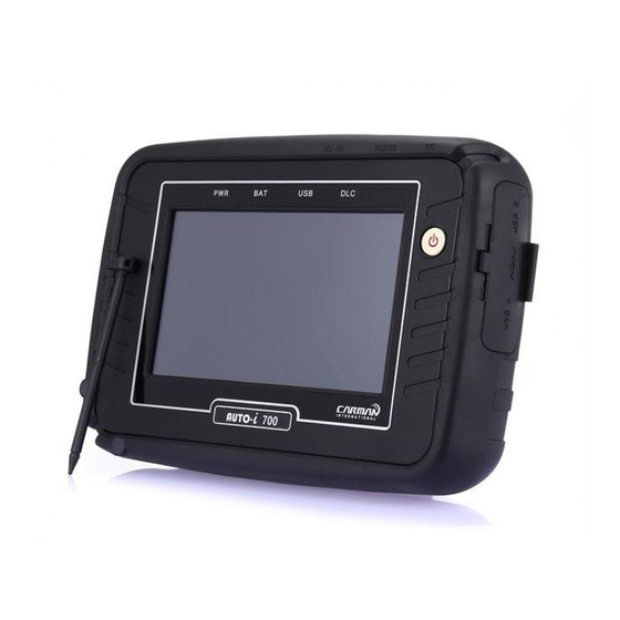
AUTO-i 700 Chapter 1: General Descriptions 6.Component Figures and Descriptions 6-1. User Guide AUTO-i 700 User Guide Be sure to read the guide before using the product.. 6-2. Main Module AUTO-i 700 Main Module * The exterior might be changed without any notice in advance. - Page 12 1. Power connector: It is for a AC/DC power adaptor and a cigar jack. 2. RS-232 connector: It is for the optional product that CARMAN IT sells. 3. RJ45: It is not supported just now. (Later it is supposed to support.) ! Please do not insert a LAN cable.
- Page 13 6-4. AUTO-i 700 Carrying Case AUTO-i 700 Carrying Case AUTO-i 700 includes a number of adaptors and cables for diagnosing vehicles. When the product is not in use, store it in the supplied carrying case to prevent damage and loss.
- Page 14 6-6. Rubber Shroud (fit to the main body initially) - The color of rubber shroud can be changed according to user Rubber Shroud The rubber shroud protects AUTO-i 700 from external electrical and physical impact. 6-7. USB Cable USB Cable The USB cable connects the USB ports of AUTO-i700 and your PC to download the diagnosis software or save captured files to your PC.
- Page 15 AUTO-i 700 Chapter 1: General Descriptions 6-8. CD *Components of CD - Installation Driver - PC Program - PDF Program - Basic Diagnostic Data - User Guide 6-9. Wi-Fi USB Dongle -Newest diagnostic data can be updated automatically via Wi-Fi(USB A Type). Also, without wire, captured screens in the scanner can be printed via PC that is connected to a printer.
- Page 16 6-10. Cigarette Cable Cigarette Cable This cigarette cable connects AUTO-i 700 and a vehicle so that it can supply power. AUTO-i 700 has internal battery inside so it can boot without other power but if power of batter is low and it is not charged, you can use cigarette cable or AC/DC power adapter.
- Page 17 AUTO-i 700 Chapter 1: General Descriptions 6-12. DLC Cable DLC Cable The DLC cable is also called the OBD-II cable. All vehicles released recently have built-in OBD-II connectors compatible to the OBD-II specification. It is possible to diagnose new model vehicles by directly connecting the DLC cable. It is not necessary to connect any additional power source as power is feed through the diagnostic connector.
- Page 18 AUTO-i 700 Chapter 1: General Descriptions 6-14DLC Adapter The DLC adapter is used to diagnose vehicles by connecting it to the DLC main connector. As there are similar shaped adapters, make sure to check the vehicle manufacturer name on the adapter before use.
- Page 19 AUTO-i 700 Chapter 1: General Descriptions DAEWOO LPG CABLEHYUNDAI,MITSUBISHI CABLE (12P) 2) Cable for registering trans meter codes to Korean vehicles. KIA KEYLESS CABLE HYUNDAI KEYLESS CABLE...
- Page 20 AUTO-i 700 Chapter 1: General Descriptions 3) Japanese kit TOYOTA, LEXUS ADAPTOR (17P"R")TOYOTA, LEXUS ADAPTOR (17P"C") HONDA ADAPTOR (3P)HONDA ADAPTOR (5P) SUBARU ADAPTOR (16P-9P)MAZDA "C" ADAPTOR (17P) MAZDA ADAPTOR (6P + 1P)NISSAN ADAPTOR (14P)
- Page 21 AUTO-i 700 Chapter 1: General Descriptions MITSUBISHI ADAPTOR (12P) MITSUBISHI CABLE (12P+16P)
- Page 22 AUTO-i 700 Chapter 1: General Descriptions 4) European kit Mercedes Benz Board (38P) Mercedes Benz Cable (3 liners) Peugeot /Citroen Cable (2P) Audi / VW Cable (2+2P) Fiat Cable (3P) Opel Adapter (10P) BMW Adapter (20P)
- Page 23 AUTO-i 700 Chapter 1: General Descriptions 5) USA/ Australian kit Ford Cable (20P) Holden Cable (6P)
-
Page 24: Power Supply
AUTO-i 700 Chapter 1: General Descriptions 7. Power Supply 1. Cigarette Lighter Power Cable Power is fed through the cigarette lighter power cable. However, when the vehicle ignition switch is in the “OFF” position or upon starting a vehicle, power is not supplied to the cigarette lighter socket. -
Page 25: Chapter 2Menu Configuration
Voltage mismatch between the ECU and AUTO-i 700 may cause a communication error. 1-2.Before using the system, make sure to download the diagnosis program. -
Page 26: Menu Description
03. DOWNLOAD - In this menu, AUTO-i700 can connect to PC so that it can upgrade software and download saved files etc. in AUTO-i 700 to PC. 04. CONFIG - In this menu, you can check the system display unit, favorite maker setting, screen setting, time setting and system information 05. -
Page 27: Icons
AUTO-i 700 Chapter 2: Menu Configuration 3. Icons on Main Screen 3-1 Icons on main screen ① ② ③ ④ 1. Clock This displays the current time. 2. FAT32 - It shows only removable memory disk which is formatted with FAT32. - Page 28 4. Back: Pressing this button to return to the previous screen. 5. Autoselect Car Menu (Press this button to Activate. then the color of icon changes to white.) - Activate Autoselect Car Menu and AUTO-i 700 starts from the Menu screen directly.
-
Page 29: Chapter 3 Configuration
AUTO-i 700 Chapter 3: Configuration 1. Display - You can set up language and brightness of LCD. - Setting brightness will improve efficiency of work in a dark or bright place. Also, language can be selected according to a user. -
Page 30: Graph
AUTO-i 700 Chapter 3: Configuration 2. Graph - Graph– 2-1.Init 1: Standard default setup. 2-2. Init 2: Background color in Default 1 is white. 2-3. Save: After changing settings, save with [save] icon on the bottom of the screen so that changed setting values can be displayed. -
Page 31: Maker
AUTO-i 700 Chapter 3: Configuration 3. Maker - It is possible to select your favorite vehicle maker to be displayed on top in the diagnosismenu.. - This function can save time to search for the desired vehicle maker whenever the diagnosis is made. -
Page 32: Time Set
AUTO-i 700 Chapter 3: Configuration 4.Time Set - You can change the date and time stored in the internal memory. - The time stored in this menu is used when saving a file or executing other functions. - User can adjust time and date of the scanner. -
Page 33: Wi-Fi
AUTO-i 700 Chapter 3: Configuration 5. Wi-Fi - Choose your Wi-Fi router on the list for your Wi-Fi connection. - Wi-Fi – 5-1 REFRASH – Displays all connectable Wi-Fi routers around. 5-2 CONNECT– Connect wireless communication with your selected router. -
Page 34: Lock
AUTO-i 700 Chapter 3: Configuration 6.LOCK You can set the lock to be used only by a specified user. -Enter Password- 6-1 set the password The password can be set to a 4-digit number. -비밀번호 설정-... - Page 35 LOCK can set On and Off, password can be changed. ※ Caution :LOCK key is on Off, set password is deleted. -LOCK screen- -Change the password- ※Caution : when you forget the password, please contact to CARMAN IT head office.
-
Page 36: Information
AUTO-i 700 Chapter 3: Configuration 7. Information You can input your information or check system & License information. -Information- 7-1. Press the Information button. Then, the information is shown so you can check system and License. - Page 37 AUTO-i 700 Chapter 3: Configuration -Information- 7-2. User information is shown and you can edit and save information. 7-3. In order to change the information.Please select a item to edit, click the edit button on below bar and input information.
-
Page 38: Chapter 4Utility
AUTO-i 700 Chapter 4: Utility This function is to check flight records, text shots and screen captures etc. 1. Flight Record - You can save parameter data of a vehicle to analyze it. (Refer to P52) - You can save the desired parameter data. -
Page 39: Textshot
AUTO-i 700 Chapter 4: Utility 2. Text Shot - You can save a measured value you select among system error code and parameter data by choosing specific time during diagnosis. and you can use the values of specific time to analyzation. -
Page 40: Screen Capture
AUTO-i 700 Chapter 4: Utility 3. Screen Capture - Press the button on the left upper side if you need to capture screens while using. - Conveniently, screens are saved. - Screen Capture- 3-1.Full Screen: Press this button to show the saved files on a full screen. - Page 41 AUTO-i 700 Chapter 4: Utility -Full Screen - # Red Marker function is available in the full screen mode. ① :Press this button to activate the red marker function. Then, click on the screen and drag it to make a mark.
-
Page 42: Chapter 5Diagnosis Menu
-Location of OBD-II diagnostic connector- 2. Use the DLC main cable to connect the vehicle's diagnostic connector and AUTO-i 700. 3. Turn on AUTO-i 700 -If power is not feed through the diagnostic connector and the AUTO-i 700 battery is not fully charged, you need to connect an additional power supply (vehicle battery or cigarette lighter power cable, etc.). - Page 43 AUTO-i 700 Chapter 5:Diagnosis Menu 5. Select the maker of the vehicle to diagnose. -Vehicle Maker Selection – * RECENT LIST:Save ten latest diagnosed vehicles to simplify same procedures. * GUIDE: Provides “Demo Mode”, “VIN Decoder”, “PIN Code Generator”, Hardware Check”...
- Page 44 AUTO-i 700 - Vehicle Model selection – Chapter 5: Diagnosis Menu 7. Select the system to be diagnose. -System Selection- *Diagnostic Connector Type (TOYOTA models use same connectors with Lexus models.) 1. 16-pin connector: common OBD-II connector 2. Semi-circular connector: Toyota 17-pin C-type connector 3.Rectangular connector: Toyota 17-pin R-type connector...
-
Page 45: Chapter 6Vehicle Diagnosis
Also, the description for DTCs is displayed as well to help you service your vehicle. In order to diagnose DTC correctly, please check the connection between connector and AUTO-i 700. Please refer to Chapter5: Diagnosis menu and check details such as Vehicle maker, model and displacement etc. - Page 46 AUTO-i 700 Chapter 6:Vehicle Diagnosis If it does not show a menu like page 43 and shows "Communication Error" or does not communicate stably, please check first status of the target car or connection of cables. -Diagnostic Trouble Code- 2. The DTC search screen appears. Now, you can check current and history DTCs and erase them.
- Page 47 AUTO-i 700 Chapter 6:Vehicle Diagnosis - DTC - 3-1. DTC - Press this button to check current DTCs. - In the case of MIL type vehicle, you can check codes through the DTC list. 3-2. History DTC - Press this button to check history DTCs.
-
Page 48: Erase/Reset Dtc
AUTO-i 700 Chapter 6:Vehicle Diagnosis 2. Erase/Reset DTC If you select a car and a system correctly on the menu and if communication with a car works successfully, it shows the DIAG MENU like a picture below. Press the ERASE/RESET DTC button. -
Page 49: Parameterdata
AUTO-i 700 Chapter 6:Vehicle Diagnosis 3.Parameter Data - In the PARAMETER DATA menu, the module can communicate with the vehicle ECU to check data and control values of each sensor of the selected system and to check conditions of various switches and actuators. - Page 50 AUTO-i 700 Chapter 6:Vehicle Diagnosis The Parameter data list is displayed as shown in the below picture -Parameter Data-- Graph mode: Press this button to check parameter data in graphs.. - Press this button to check parameter data in graphs.It is helpful to convert the current vehicle data to graphs for tendency analysis.
- Page 51 AUTO-i 700 Chapter 6:Vehicle Diagnosis Unit Conversion: You can change the unit of data that is expressed when communication withthe vehicle. - The unit of speed, temperature, angle, pressure can be confirmed or changed. - Press “▼” button next to the unit, you can also change each of it.
- Page 52 AUTO-i 700 Chapter 6:Vehicle Diagnosis 1) It is possible to change the display units all at once according to the region that uses“Metric” or “Yard-Pound” system. 2) After changing the display unit, click the Save button to save your modification.
- Page 53 AUTO-i 700 Chapter 6:Vehicle Diagnosis If you use the fix function, values are changed only for the fixed items so you can measure changed values faster and can diagnose more precisely. - Graph Mode:This function is to check parameter data in graph forms for tendency analysis.
- Page 54 AUTO-i 700 Chapter 6:Vehicle Diagnosis - Stop: More accurate failure analysis is available at any point in time Using the cursor appears in a still image, you can see the value of the target area. -File Mode: Press this button to save data or check the saved data.
- Page 55 AUTO-i 700 Chapter 6:Vehicle Diagnosis Only selected Flight record data by user is saved. On the other hand, if a user selects some list, only the selected list is saved but if a user select nothing, all list is saved.
- Page 56 AUTO-i 700 Chapter 6:Vehicle Diagnosis - Compare :Based on the reference sensor data (normal vehicle) and the current vehicle sensor data value, the comparison is made using the maximum and minimum values of the reference vehicle. Saving reference sensor data :Save sensor data by existing text shot button.
- Page 57 AUTO-i 700 Chapter 6:Vehicle Diagnosis Comparison of sensor data: When a value outside the reference range, it is displayed in red. -Apply comparative data- ※ The value displayed from the comparison value may be different from the reference value range of actual sensor. Please use for reference only.
-
Page 58: Actuator Test
AUTO-i 700 Chapter 6:Vehicle Diagnosis 4. ACTUATOR TEST - In this menu, you can start and stop actuators and switches forcibly to diagnose them. - The actuation function is available depending on vehicle makers and models. - Actuator Test- 1. If a car and a system are selected correctly in the Vehicle Diagnosis menu and communication with vehicle is stable, the above picture will be shown Select a Actuator Test. - Page 59 AUTO-i 700 Chapter 6:Vehicle Diagnosis 2. The screen as below appears. -Actuator- 3. Press the start button after selecting a item. - Figure 3-1 Actuator Start & Stop –...
- Page 60 AUTO-i 700 Chapter 6:Vehicle Diagnosis - Before starting actuation, make sure to check the operating condition to inspect the system in the proper condition. - The actuator time differs by the actuated items. 4. Press the Stop button to stop the actuator function.
-
Page 61: Resetting Adaptive Values
AUTO-i 700 Chapter 6:Vehicle Diagnosis 5. Resetting Adaptive Values. - The resetting adaptive values initiates ECU by clearing values of sets in ECU. - The clearing learning values may be different depend on car makers and models. -
Page 62: Evap. Leakage Test
AUTO-i 700 Chapter 6:Vehicle Diagnosis 6. Evap. Leakage Test - Press this button to check if there is leakage from a oil tank... -
Page 63: Pcm Lock(Mec) Setting
AUTO-i 700 Chapter 6:Vehicle Diagnosis 7. PCM Lock(MEC) Setting - This function is to prevent data or programs from adjustment. - System information differs from depend on car makers and models. -
Page 64: Misfire Delay Reason
AUTO-i 700 Chapter 6: Vehicle Diagnosis 8. Misfire Delay Reason - This function is to check the number of misfire in each cylinders. - System information differs from depend on car makers and models. -
Page 65: System Information
AUTO-i 700 Chapter 6:Vehicle Diagnosis 9.System Information -System Information shows information related with system such as system model and software version etc. - System information differs from depend on car makers and models. -
Page 66: Chapter 7Obd-Ii/Eobd Diagnosis Menu
AUTO-i 700 Chapter 7: OBD-II/EOBDDiagnosis Menu 1. OBD-II/EOBDOverview ■ Purpose ofOBD-II/EOBD - OBD-II/EOBDis intended to find what caused the emission to increase, diagnose the part of thecause and light the warning lamp in order to provide faster and more precise repair. -
Page 67: How To Connect Self-Diagnostic Connector And Select Diagnosis Program
- As OBD-II vehicles feed power through the diagnostic connector to the module, they do not need any additional power supply.. 4. Press the OBD-II/EOBD button on main screen of AUTO-i 700 to see diagnosis items. 5. Diagnosis function includes Auto-searching, ISO9141-2/KWP2000, J1850PWM/J 1850VPW, CAN communication(Figure 5-1) etc. - Page 68 AUTO-i 700 Chapter 7: OBD-II/EOBDDiagnosis Menu 5-1) Communication screen - Communication- 5-2) Connect a OBD2 16pin connector. (DLC main cable) - Connect OBD2 16pin connector -...
-
Page 69: Chapter 8Obd-Ii/Eobd Vehicle Diagnosis
AUTO-i 700 Chapter 8: OBD-II/EOBDVehicle Diagnosis 1. READINESS TEST -The readiness test tries making communication with your vehicle to review general items of ECU modules that response. -Readiness Test Selection- 1-1. If communication with the vehicle is established successfully, the menu above appears. - Page 70 AUTO-i 700 Chapter 8: OBD-II/EOBDVehicle Diagnosis -Readiness Test- *Results 1. NOT CMPLTD: The test has not been completed. - This appears when the test was not completed owing to the abnormal ECU or sensorrequired to display the test result.. 2. COMPLETED: The test has been completed.
-
Page 71: Parameter Data
AUTO-i 700 Chapter 8: OBD-II/EOBDVehicle Diagnosis 2. PARAMETER DATA -You can check the PARAMETER DATA specified by the OBD-II/EOBD standard in this menu. -PARAMETER DATA Selection - 2-1. If communication with the vehicle is established successfully, the above menu appears. Select the PARAMETER DATA. - Page 72 AUTO-i 700 Chapter 8: OBD-II/EOBDVehicle Diagnosis -OBD-II/EOBD PARAMETER DATA- 2-2 Parameter data are listed on the screen as shown in above figure. you can check values of each parameter. -Refer to the description from "Chapter6 vehicle diagnosis for each button`s function.
-
Page 73: Diagnostic Trouble Codes
AUTO-i 700 Chapter 8: OBD-II/EOBD Vehicle Diagnosis 3. Diagnostic Trouble Codes -Press this button to check trouble code of current vehicle. -DTC selection- 3-1.Communication withe vehicle is properly establlished, the above menu appears. Select Diagnostic Trouble Codes. If the above menu is not appeared and Communication cannot be established, check the vehicle condition and the connection status of the diagnostic connector again. - Page 74 AUTO-i 700 Chapter 8: OBD-II/EOBDVehicle Diagnosis -DTC- 3-2. DTCs are listed on the screen as shown in above figure. You can check values of each parameter. - Refer to the description of "Chapter6 Vehicle Diagnosis" for each button`s function. - Parameter data items in OBD-II communication may be different fromparameterdata items that are checked by selecting cars becauseparameterdataitems in OBD-II standard are provided.
-
Page 75: Erase/Reset Dtc
AUTO-i 700 Chapter 8: OBD-II/EOBDVehicle Diagnosis 4. Erase/Reset DTC 1. Select a car model and system in the diagnosis menu. Then, if communication with the vehicle is established successfully, the menu shown in Figure of Page65 appears. Select the ERASE/RESET DTC button. -
Page 76: Monitoring Test Results
AUTO-i 700 Chapter 8: OBD-II/EOBDVehicle Diagnosis 5. Monitoring Test Results - This menu displays the monitoring test results while the vehicle is being normally operated. - To test systems and units of different manufacturers, it is required to specify test IDs and component IDs. - Page 77 AUTO-i 700 Chapter 8: OBD-II/EOBDVehicle Diagnosis...
- Page 78 AUTO-i 700 Chapter 8: OBD-II/EOBDVehicle Diagnosis...
-
Page 79: Bi-Directional Control
AUTO-i 700 Chapter 8: OBD-II/EOBDVehicle Diagnosis 6. BI-Directional Control - You can control and test functions related with OBD-II system. - BI-Directional Control 6-1.If communication wih the vehicle is established successfully, the menu above appears. Select BI-DIRECTIONAL CONTROL. If no menu like picture above is displayed or communication cannot be established, check the vehicle condition and the connection status of the diagnostic connector again. -
Page 80: Vehicle Information
AUTO-i 700 Chapter 8: OBD-II/EOBDVehicle Diagnosis VEHICLE INFORMATION - This menu displays information of the ECU installed in your vehicle. - You can check only the ECU that provides its module information. -VEHICLE INFORMATION Selection- 7-1. If communication wih the vehicle is established successfully, the menu above appears. - Page 81 AUTO-i 700 Chapter 8: OBD-II/EOBDVehicle Diagnosis - This menu displays information of the ECU installed in your vehicle like the picture above. - Press the ENTER button to check system information in detail.
-
Page 82: Chapter 9 Program Download
1. How to Install download program. - Use only the USB supplied by our company to connect the PC and AUTO-i 700. - Select the DOWNLOAD button in main screen of AUTO-i 700. - Download new software after check how to download it in our website. - Page 83 AUTO-i 700 Chapter 9: Program Download 3) Screen will show the below. 4)Save a update program file into the Update folder in AUTO-i 700. After saving the file, please remove the USB cable from scanner.
- Page 84 AUTO-i 700 Chapter 9: Program Download 5) It is updating automatically by removing USB cable. Please wait the updated number to be full. 6) It is updating automatically. After update completed, please click the Exit button.
- Page 85 AUTO-i 700 Chapter 9: Program Download 2-2 HowtoupdateAUTO-i 700By USB memory stick 1)Insert USB memory stick containing a update program into USB-A port. 2) Click the DOWNLOAD button. 3) AUTO-i 700 is checking the USB memory stick automatically.
- Page 86 AUTO-i 700 Chapter 9: Program Download 4) AUTO-i 700 copies a program in the USB stick automatically and shows you a screen as below to remove USB memory stick. 5) It is updating automatically by removing USB stick Please wait the updated number to be full.
- Page 87 AUTO-i 700 Chapter 9: Program Download 2-3 How to update AUTO-i 700 By Wi-Fi dongle 1) Put Wi-Fi dongle into USB A port. (Ref. 33 page) 2) Press “Download” button and “OK” button. 3) Click Checkbox and press “Download” button.
- Page 88 AUTO-i 700 Chapter 9: Program Download 4) It is updating automatically Please wait the updated number to be full. 5) It is updating automatically. After update completed, please click the Exit button.
-
Page 89: Appendix: Registration
AUTO-i 700 Appendix: Registration # We explain how to register using windows 7. How to register? # You can register on website or where you purchase our products. # Website address for registration: http://www.carmanit.com How to register through website 1. Input http://www.carmanit.com into theaddress bar on browsers. -
Page 90: Q&A
- If the vehicle diagnostic cables cannot supply power from vehicle, connect the cigarette lighter power cable for power. - If there is electric potential difference between AUTO-i 700 batteries and vehicle batteries, communication is not available. * If the problem is not solved, a hardware of scanner or a vehicle may be out of order. -
Page 91: Certificate Of Information And Communication Equipment
Manufacturer ID: MSIP-REM-CMi-AUTO-i700 Certificate Date: Aug. 2014 COPYRIGHT ⓒ by CARMAN IT Co., Ltd. All right reserved. No part of this publication may be reproduced, stored in a retrieval system, or in any form, or by any means, electronic, mechanical, photocopying, recording or... -
Page 92: Warranty Card
3. Repairs not covered by this warranty will be performed at the current cost for parts and labor. In no event will CARMAN IT Co. Ltd’s liability exceed the price paid for the product from direct, indirect, special, incidental or, consequential damages resulting from the use of this product, its accompanying software, or its documentation without obligation to notify any individual or entity.
Need help?
Do you have a question about the AUTO-i 700 and is the answer not in the manual?
Questions and answers