Table of Contents
Advertisement
Quick Links
Advertisement
Table of Contents

Related Manuals for Rtelligent R60-IO


Summary of Contents for Rtelligent R60-IO
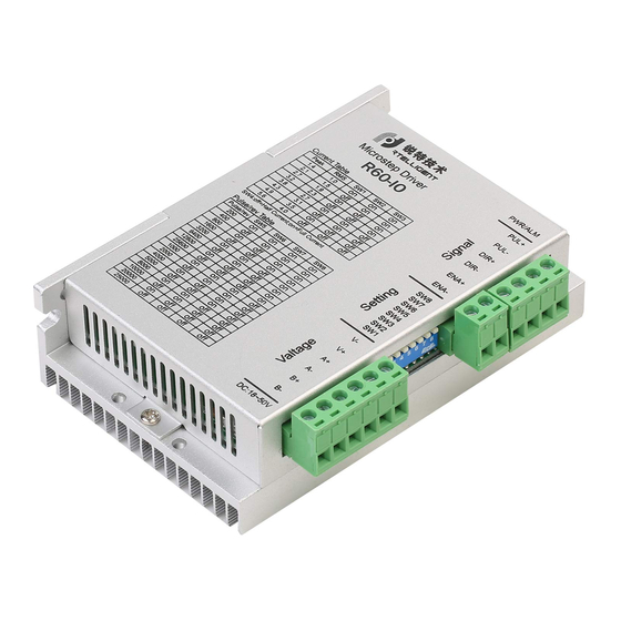
- Page 1 R60-IO User Manual Shenzhen Rtelligent Mechanical Electrical Technology Co., Ltd.
-
Page 2: Table Of Contents
R60-IO User Manual -1- Contents 1. Product Overview..............................2 Application Environment and Installation...................... 2 Environmental requirement........................2 Drive installation dimensions........................3 Drive Port and Connection..........................4 Port function description........................... 4 Power supply input............................ 4 Motor connection............................. 5 Control signal connection........................6 3.4.1 IN Port: connection for pulse command..................6 3.4.2... -
Page 3: Product Overview
The R60-IO driver is a switch input control driver designed by Rtelligent for potentiometer speed control. The drive integrates a motion control module to support IO trigger fixed speed motion. -
Page 4: Drive Installation Dimensions
R60-IO User Manual -3- Installation environment Avoid dust, oil and corrosive environment 0.5G(4.9m/s ) Max Vibration 0℃ ~ 45℃ / 90% RH or less (no condensation) Operating temperature/humidity -10℃ ~ 70℃ Storage and transportation temperature: Cooling Natural cooling / away from the heat source... -
Page 5: Drive Port And Connection
R60-IO User Manual -4- 3. Drive Port and Connection 3.1 Port function description Function Grade Definition Remarks Input AC power supply DC 24~48V Power supply input port Input AC power supply connect two terminals of motor’s phase-B winding Motor connection port connect two terminals of motor’s phase-A winding... -
Page 6: Motor Connection
6-wire center shaft head 6-wire series The matching motor of the R60-IO drive is the low resistance and low inductance hybrid stepper motor. The common 2-phase stepper motor’s lead number are 4, 8 and 6. There is only one connection mode for 4 leads motor. -
Page 7: Control Signal Connection
When IN1 and IN2 are both on, the motor will stop running. Note: The IO driver defaults to mode 1. If you need to adjust, please explain to Rtelligent. 3.4.2 ENA port: used to enable or disable. -
Page 8: The Setting Of Dip Switches And Operating Parameters
R60-IO User Manual -7- internal photocoupler is turned on, the driver will cut off the current of each phase of the motor to make the motor in a free state. At this time, the step pulse is not responded. When the motor is in an error state, the ENA input can be used to restart the drive. First remove the fault, then input a falling edge signal to the ENA terminal, the driver can restart the power part, and the motor excites. -
Page 9: Acceleration Selection
R60-IO User Manual -8- 6400 12800 25600 1000 2000 4000 5000 8000 10000 20000 25000 DIP SW5, SW6, SW7, SW8 are used to set the speed when the motor is triggered. Built-in S-type acceleration and deceleration. When the switch is closed, the motor accelerates to the set speed. -
Page 10: Common Faults And Troubleshooting
R60-IO User Manual -9- 6. Common Faults and Troubleshooting Phenomenon Possible situations Solutions Check the power supply circuit for normal Power indicator is off power supply The motor rotor is locked but the Pulse signal is weak; increase the signal... -
Page 11: Appendix A. Guarantee Clause
R60-IO User Manual -10- Check whether there is any solder ball due Internal resistance between to excessive addition of solder on the wire terminals is too large connections Acceleration deceleration Reduce command acceleration or increase time is too short drive filtering parameters...
Need help?
Do you have a question about the R60-IO and is the answer not in the manual?
Questions and answers