
Subscribe to Our Youtube Channel
Related Manuals for Rtelligent EC Series


Summary of Contents for Rtelligent EC Series
- Page 1 ECR60/ECT60 User manual ECR60/ECT60 User manual Shenzhen ReitE Electrical and Mechanical Technology Co., Ltd.
-
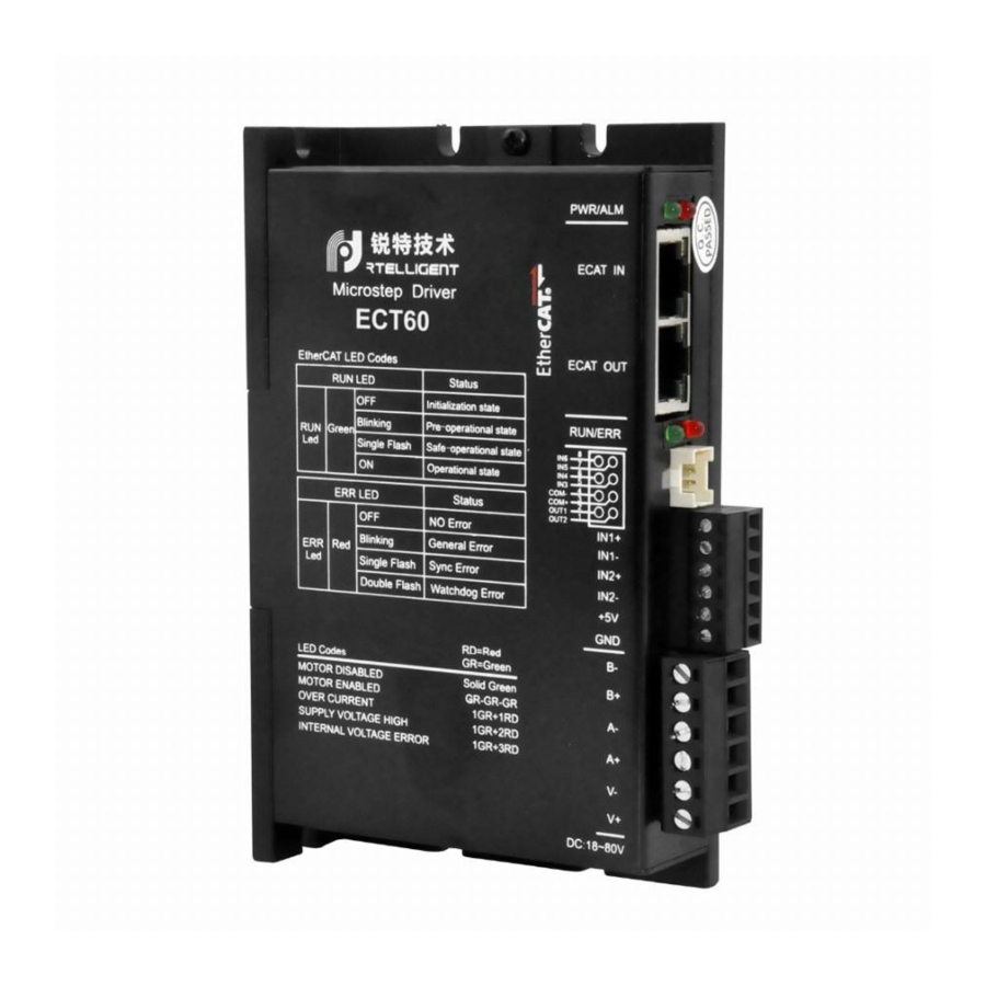
Page 2: Product Introduction
第一章 Drive description 1.1 Product introduction Thank you for choosing the Reiter EC series stepper motor driver. The EC Series is a high-performance bus-controlled stepper motor driver with the ability to integrate intelligent motion controllers. The EC Series EtherCAT drives can be operated as standard EtherCAT slaves and support CoE (CANopen over EtherCAT). -
Page 3: Electrical Characteristics
ECR60/ECT60 User manual 30V, maximum infusion or pull-out current 100mA, common cathode docking method. Electrical characteristics ECR60 Electrical characteristics Product model ECR60 ECT60 Output current 0.5 to 6A Supply voltage 24 to 80VDC Matching motors Below 86 base Encoder interface Incremental orthogonal encoder, 4x Encoder resolution 1000 to 65535 pulses/revolution... -
Page 4: Power And Motor
ECR60/ECT60 User manual 1.2 Power and motor Identity Description V-plus DC-powered, positive, V-connected power supply negative. The voltage is 24 to 80VDC. Due to the effect of the anti-electric potential, the customer needs to reserve a certain amount of voltage margin when using A-plus Two-phase stepper motor winding interface Any pair of A-plus, A--... -
Page 5: Digital Input Port
ECR60/ECT60 User manual 1.3 Digital input and output ports The ECR60 stepper driver has 6 photoelectric isolated digital inputs and2 photoelectric isolated digital ports. ECT60 Because IN1 and IN2 are assigned to orthogonal encoder interfaces, they can no longer be used for other input port functions and will not work for in1, IN2 functional settings. - Page 6 ECR60/ECT60 User manual IN1+ IN1- OUT1 IN2+ IN2- OUT2 +24V IN1plus/IN1-, IN2 plus /IN2- differential input terminals IN1,IN2 is reserved external motor encoder, constitutes a closed-loop system, ECR60 can not receive encoder signal. ECT60 is only allowed. 5V differential input 5V single-ended input...
- Page 7 ECR60/ECT60 User manual 脉冲的单端驱动 上位控制器 上位控制器 伺服驱动器 伺 DC5V PULSE+ IN1+ DC24V PULSE+ IN1- PULSE- PULSE- SIGN+ IN2+ SIGN+ IN2- SIGN- SIGN- Note: When the IN1 and IN2 ports use the 24V input, please string the2K limiting resistance externally, otherwise the drive will be damaged. IN3to IN6 single-ended input terminals Taking IN3 as an example, the IN3toIN6 interface circuits are the same.
- Page 8 ECR60/ECT60 User manual Note: PNP input is not supported...
-
Page 9: Digital Output Port
ECR60/ECT60 User manual Digital output port The ECR60/ECT60 contains two photoelectric isolation output signals. OUT1 has an output current capacity of 30mA. OUT2 has an output current capacity of 150mA. The digital output port is all normally open by default, the function of the output port can be selected by object dictionary 2005, and the object dictionary 2006 is used to set the polarity of the set output port. - Page 10 ECR60/ECT60 User manual 驱动器 OUT1 OUT2 Take OUT1 as an example, the OUT1to OUT2 interface circuit is the same. When the upper unit is entered for a relay: 输出电路外接继电器 输出电路外接光耦 DC12-24V DC12-2 输出电路外接继电器 输出电路外接光耦 Correct wiring diagram: 伺服驱动器 DC12-24V 伺服驱动器 DC12-24V DC12-24V 伺服驱动器...
- Page 11 电器 输出电路外接光耦 ECR60/ECT60 User manual 未接入限流电阻 DC12-24V DC12-24V 驱动器 伺服驱动器 伺服驱动器 光耦 光耦 OUT1 OUT1 外部地 外部地 续流二极管极性错误 伺服驱动器 DC12-24V 继电器 外部地...
- Page 12 ECR60/ECT60 User manual 1.4 Connect etherCAT Use cat5E (or higher) network cables. The Ethernet input inn IN is connected to the Ethernet output interface OUT of the controller or the previous driver on the bus. The Ethernet output interface OUT is connected to the Ethernet input inthe for the next driver on the bus.
- Page 13 ECR60/ECT60 User manual Slow flash: 200ms, 200ms (2.5Hz). So loop. Single flash: 200ms, 1s. So loop. Double flash: bright 200ms, 200ms, 200ms, 1s. So loop.
-
Page 14: Alarm Code
ECR60/ECT60 User manual 1.5 EtherCAT site address The EC series supports two ways to set the slave address: the object dictionary 0x2150 set the site alias and the ESC set site alias, and selected by the object dictionary 0x2151. The default 0x2151 is 0, and the node address is allocated through the master and saved to EEPROM. -
Page 15: Mechanical Size
ECR60/ECT60 User manual 1.7 Mechanical size... -
Page 16: Software Version
ECR60/ECT60 User manual 第二章 Parameter description and settings 2.1 General use parameter 0x1000 Unit Type Object Type Data Type Access Type PDO Mapping Default Value UNSIgned 0x00040192 Bit 0-15: Device profile number 0x0192: CiA402 Bit 16-31: Additional information 0x0004: Stepper Drive 0x1001 Appliance Name Displays the current drive model name. -
Page 17: Save Parameters
ECR60/ECT60 User manual Save parameters Sub-index of object dictionary 0x1010: 01 writes 1, which saves the current parameter. When saving the parameters, stop the motor first, and then save the parameters. The data structure is as follows: Index Sub-index Name PDO mapping The default value 1010... -
Page 18: Manufacturer-Specific Objects
ECR60/ECT60 User manual 2.2 Manufacturer-specific objects 0x2000 operating current Object Name Propert Type Range The default Unit dictionar value 0x2000 Peak Current R/W/S UINT 100 to 6000 3000 The object is used to set the sine peak current for the run of the stepper motor open ring. - Page 19 ECR60/ECT60 User manual 0x2003 Idle Current Percent R/W/S UINT 0to100 This object is used to set the percentage of the operating current set by 0x2000 when the motor stops running into standby when the motor is in standby while running on the ring of the stepper motor.
- Page 20 ECR60/ECT60 User manual 0x2005 output port function Object Name Propert Type Range The default Unit dictionary value 0x2005:01 Output 1 Function R/W/S UINT 0 to 3 0x2005:02 Output 2 R/W/S UINT 0 to 3 Function The ECR60 contains two output ports, which are used to set the corresponding function of the output port.
- Page 21 ECR60/ECT60 User manual...
- Page 22 ECR60/ECT60 User manual 0x2007 Input Port Function Object Name Propert Type Range Unit dictionary default value 0x2007:01 Input 1 Function R/W/S UINT 0 to8 0x2007:02 Input 2 Function R/W/S UINT 0 to8 0x2007:03 Input 3 Function R/W/S UINT 0 to8 0x2007:04 Input 4 Function R/W/S...
- Page 23 ECR60/ECT60 User manual Bit15 to Bit5 Bit4 Bit3 Bit2 Bit1 Bit0 bit6 0 - Often closed,1 - Always open...
- Page 24 ECR60/ECT60 User manual 0x2009 filter time Object Name Property Type Range The default Unit dictionar value 0x2009 Filter Time R/W/S UINT 0to25600 6400 The ECR60 has a sliding average filter built in, which is used to set the time of the sliding average filter.
- Page 25 ECR60/ECT60 User manual 0x200B:02 Iloop_Kp R/W/S UINT 100 to 1000 This register cannot be set 100 to when 0x200B:01 is 1. 65535 At 0, you can set it 0x200B:03 Iloop_Ki R/W/S UINT 0 to 0 10000 0x200B:04 Iloop_Kc R/W/S UINT 0 to Anti-integration saturation 1024...
- Page 26 ECR60/ECT60 User manual Units:mH 0x200C:04 Resistance Set R/W/S UINT 0 to 0 1000 Motor winding 10000 resistance value Unit:mOhm 0x200C:05 Ingrace Set R/W/S UINT 1 to 10 Motor winding inductor value Units:mH 0x200C:06 BEMF R/W/S UINT 0 to ECT60 coefficientMF 1000 Open ring and servo mode1: The ECR60 open-loop control stepper motor and The ECT60 operate in servo mode 1...
- Page 27 ECR60/ECT60 User manual...
- Page 28 ECR60/ECT60 User manual 0x200D Run Reverse Object Name Property Type Range The default Unit dictionar value 0x200D Invert motor R/W/S UINT 0to1 direction If the positive direction of the motor is not consistent with the system requirements, the object can reverse the direction of operation of the motor without modifying the motor wiring.
- Page 29 ECR60/ECT60 User manual 0x200F internal status code Object Name Propert Type dictionary default value 0x200F Status Code UINT This object shows the current state code of the drive, with each bit of the object corresponding to a state. Status State Code 0x0001 Drive enable...
- Page 30 ECR60/ECT60 User manual 0x2011 Control mode R/W/S UINT 0to2 Set the operating mode of the stepper motor. 0 - Open ring operation 1 - Closed-loop operation 2- Closed-loop operation/FOC mode The ECR60 can only operate in open-loop mode, setting other values that are invalid. 0x2020 encoder resolution Object Name...
- Page 31 ECR60/ECT60 User manual 0x2022 Position Trae Error R/W/S UINT 1000to65535 4000 Pulse/rev Limit When the operating mode of the stepper motor is closed, when the position error exceeds this setting, the motor will alarm and disconnect the enable. This parameter is set immediately after it takes effect.
- Page 32 ECR60/ECT60 User manual value 0x2024:01 InPosMod R/W/S UINT 0 to10000 2000 Signal determination mode in place 0 - Detection at all times 1 - Detection after pulse command stop 0x2024:02 InPosCnt R/W/S UINT 0 to 1000 When the position error is less than the set pulse value and 0x2024:03 InPosTime...
- Page 33 ECR60/ECT60 User manual dictionary default value 0x2026:01 PVIA_Kp R/W/S UINT 0 to 0 2000 Position Proportional Gain: 10000 Adjusting motor position response rigidity 0x2026:02 PVIA_Ki R/W/S UINT Integral gain to eliminate 1000 positional errors when the motor is stationary. 0x2026:03 PVIA_Kv1 R/W/S UINT...
- Page 34 ECR60/ECT60 User manual Bus voltage value (V) - object value /100; 0x2049 input level Object Name Propert Type Range The default Unit dictionary value 0x2049 Input Level UINT Show the physical level of the current IO input Bit15 to bit6 Bit5 Bit4 Bit3...
- Page 35 ECR60/ECT60 User manual 0x204A output level Object Name Propert Type Range The default Unit dictionary value 0x204A Output Level UINT Show the current physical level of the output port Bit15 to bit2 Bit1 Bit0 OUT2 OUT1 0 - indicates that the current output port has output 1 - indicates that the current output port has no output 0x2060 First Resonance Point Harmonic Magnitude Object...
- Page 36 ECR60/ECT60 User manual 0x204A Phase B of First Anti-Vibration UINT 0-1024 Adjust the harmonic phase of the B-phase winding...
- Page 37 ECR60/ECT60 User manual 2.3 CIA402 Object Dictionary 0x603F fault code Object Name Property Type Range The default dictionary value 0x603F Error Code UINT When a failure occurs, the failure condition is first eliminated, and then 0x0080 is written to the control word 0x6040 to clear 0x603F. The fault code is as follows: Error Code Describe...
- Page 38 ECR60/ECT60 User manual 0x0640 Control Word This object is used to control the state of the drive and motion. Can enable/prohibit the drive, motor start, stop, clear fault, etc. Object Name Property Type Range The default dictionary value 0x6040 Control Word UINT The bit sits of the control word are defined as follows: Describe...
- Page 39 ECR60/ECT60 User manual Definitionof snr 4, 5, 6, 8, 9 in the relevant mode PP mode Name Value Describe A new target location 0- 1 Change from 0 to 1 to set a new target position Keep Absolute/relative Absolute position mode Relative position mode Time out Motor waiting to complete positioning...
-
Page 40: 0X6041 Status Word
Used to set the operating mode. Object Name Property Type Range The default dictionar value 0x6060 Mode of Operation INTEGER8 The EC Series drives support the following operating modes: Value Mode Profile Position Mode (PP) Profile Velocity Mode (PV) Homing Mode (HM) - Page 41 ECR60/ECT60 User manual Cyclic Dynamic Position Mode (CSP) 0x6061 Operating Mode Display Displays the current operating mode, defined with 0x6060. Object Name Prope Type Rang dictionar default value 0x6061 Mode of Operation Display INTEGER8 0x6064 Actual location Shows the actual position of the current motor, in Pulse Object Name Prope...
- Page 42 ECR60/ECT60 User manual In CSP mode, this target position is absolute position mode. 0x607C zero bias This object is used to set the zero sensor's offset from position 0. The unit is Pulse. Object Name Prope Type Rang dictionar default value 0x607C Home Offset...
- Page 43 ECR60/ECT60 User manual value 0x6084 Profile Deceleration INTEGER32 100000 0x6085 Quick Stop Deceleration This object is used to set PP mode, PV mode, HOME mode, when the limit, zero point and other sensors, the motor stops the reduction speed. The unit is Pulse/s. Object Name Prope...
- Page 44 ECR60/ECT60 User manual Object Name Propert Type Range dictionar default value 0x609A Homing Ense UNSIGNED32 100000...
- Page 45 ECR60/ECT60 User manual 0x60B8 probe function settings This object sets the probe function. Object Type Data Type Access Type PDO Mapping Default Value UNSIGNED16 The register bits are defined as follows: Value Definition Probe 1 is prohibited Probe 1 enables Keep Keep Keep...
- Page 46 ECR60/ECT60 User manual 0x60B9 Probe Status This object defines the probe functional state. Object Type Data Type Access Type PDO Mapping Default Value UNS116 The status bits are defined as follows: Value Definition Probe 1 is prohibited Probe 1 enables Probe 1 Rise Edge Latch : None Probe 1 rises along latch : Yes Probe 1 drops along latch : None...
- Page 47 ECR60/ECT60 User manual UNSIGNED32 0x60BC probe 2 positive latching value This object saves the position where the probe 2 rises along the latch. Object Type Data Type Access Type PDO Mapping Default Value UNSIGNED32 0x60BD probe 2 negative latching value This object saves probe 2 drops along the latchposition.
- Page 48 ECR60/ECT60 User manual 0x60FD Digital Inputs This object monitors the input port of the drive. Object Type Data Type Access Type PDO Mapping Default Value UNSIgned 0x00000000 Bit0 CW Limit 0 - Invalid 1 - Limit stake effective Bit1 CCW Limits Bit2 HOME 0 - Zero invalid...
- Page 49 ECR60/ECT60 User manual 0x60FF PV mode speed setting Speed when this object sets PV mode, in Pulse/s Object Name Propert Type Range The default Unit dictionary value 0x60FF Target Velocity DINT Pulse/s This object is 32-bit signed data, with positive and negative values representing the two directions in which the motor is running.
-
Page 50: Operating Mode
ECR60/ECT60 User manual THE EC SERIES STEP PERTERIATED DRIVES SUPPORT PP, PV, HM, CSP MODES. 2.4 CIA402 Motion Control Operating mode The ECR series EtherCAT step drive supports the following operating modes (0x6060): Profile Position (PP) Profile Velocity (PV) Cyclic Dynamic Position (CSP) - Page 51 ECR60/ECT60 User manual Start and stop When powered on, the drive is in a non-enabled state. The control word 6040h is written to 0006h, which will put the drive into the "ready to switch on" state. Indicate a new set point and start the movement by sending 001Fh to the control word of the object dictionary 6040h.
- Page 52 ECR60/ECT60 User manual Absolute/Relative Mode (bit 6) - If high, the set point is relative position mode. For example, if the front motor position is 10000 steps and the new set point is 20000, the final position will be 30000. If low, set the point absolute position mode. If the previous motor position is 10000 and the newly set position is 20000, the new position will be 20000.
- Page 53 ECR60/ECT60 User manual PV Track Speed Mode Track Speed Mode Description Track speed mode is a relatively simple mode of operation. Once the speed, acceleration and deceleration are set, the driver commands the motor to accelerate to operating speed according to the acceleration parameters, or stops the movement according to the deceleration parameters.
- Page 54 ECR60/ECT60 User manual 1 - 0 The motor has not stopped and is accelerating to V1. V1 - V2 Motor accelerates from V1 to V2 V2 - 0 Motor deceleration from V2 to 0 0 - 1 Motor stop 0 - V1 Motor stop The table above explains how the stop bit and target speed can be used together to affect the motor speed.
- Page 55 ECR60/ECT60 User manual 6040h, causing the drive to enter the "Operation Enabled" state and the motor to stop running. Start and stop To start and stop the movement, switch the control word stop bit (bit 8 bits). When the stop bit is set to 0 (000Fh), the motion starts or continues, and when the stop bit is set to 1 (010Fh), the motion stops.
- Page 56 ECR60/ECT60 User manual CSP Sync Location Mode Synchronized location mode description In this mode, the primary controller generates a position trace and sends the target location (0x607A) to the drive during each PDO update cycle. The drive feeds back the actual motor position and optional actual motor speed and torque.
-
Page 57: Probe Function
ECR60/ECT60 User manual Probe function Probe function Locks motor position information through the digital input port. The eCR60's digital input port functionality and polarity can be self-defined by 0x2007,0x2008. The probe function-related object dictionary is as follows: Index Object description 0x60B8 Probe function... - Page 58 ECR60/ECT60 User manual Probe Time Series...
- Page 59 ECR60/ECT60 User manual Serial Register changes Probe action number 60B8 Bit 0 s 1 Enable probe 1 60B8 Bit 1,4,5 Configure the up and down edge of the enable probe - 60B9 Bit 0 0 s Status "Probe 1 Enable" is placed The rising edge of the external probe signal - 60B9 Bit 1 s Status "Probe 1 rise son latch"...
- Page 60 ECR60/ECT60 User manual The rising edge of the external probe signal - 60B9 Bit 1 s Status "Probe 1 rise son latch" is placed - 60BA Probe 1 positive position is locked - 60B8 Bit 0 Probe 1 function: prohibited - 60B9 Bit Status bits cleared 0,1,2 s 0...
- Page 61 ECR60/ECT60 User manual Back to zero mode Set back to zero parameters Set back to zero speed, acceleration, zero offset and related sensor input signal. The relevant object dictionary is as follows: Object Description dictionary 0x607C Zero offset 0x6098 Zero-back method setting 0x6099 Zero-back speed 0x609A...
- Page 62 ECR60/ECT60 User manual Set the speed back to zero by 0x6099. By controlling the bit4 of the word 6040h, from 0 to 1 on the rising edge, you can start back to zero. The status of zeroback is queried by 6041 status word. Abort Back to Zero function: The back zero method is set up through the 6098h object dictionary.
- Page 63 ECR60/ECT60 User manual 2.4.6.1 Zero-back method The ECR60 drive product supports the way back to the origin of 17 to 34,35, as described below. 2.4.6.2 Method 17: 2.4.6.3 Method 18:...
- Page 64 ECR60/ECT60 User manual 2.4.6.4 Method 19: 2.4.6.5 Method 20: 2.4.6.6 Method 21:...
- Page 65 ECR60/ECT60 User manual 2.4.6.7 Method 22: 2.4.6.8 Method 23...
- Page 66 ECR60/ECT60 User manual 2.4.6.9 Method 24 2.4.6.10 Method 25:...
- Page 67 ECR60/ECT60 User manual 2.4.6.11 Method 26: 2.4.6.12 Method 27:...
- Page 68 ECR60/ECT60 User manual 2.4.6.13 Method 28: 2.4.6.14 Method 29:...
- Page 69 ECR60/ECT60 User manual 2.4.6.15 Method 30: 2.4.6.16 Method 35:...
- Page 70 ECR60/ECT60 User manual 联系 RTELLIGENT Rite Head Shenzhen Bao'an District, Guyu Nanchang Road Side Industrial Park B Building 3rd Floor Zip: 201107 Phone: : 86 (0)755 29503086 Fax: s86 (0)755 23327086 Email: sales@szruitech.com East China Office Shanghai Songjiang District Shenbrick Highway 5555, also commercial building 9, room Contact: Mr.
- Page 71 ECR60/ECT60 User manual...
Need help?
Do you have a question about the EC Series and is the answer not in the manual?
Questions and answers