
Subscribe to Our Youtube Channel
Related Manuals for Rtelligent 3R110PLUS


Summary of Contents for Rtelligent 3R110PLUS
- Page 1 3R110 Plus User Manual Digital Stepper Driver 3R110PLUS User Manual Shenzhen Rtelligent Mechanical Electrical Technology Co.,ltd szruitech.com...
-
Page 2: Table Of Contents
3R110 Plus User Manual Contents 1. Product overview............................1 1.1 Characteristic............................1 2. Application environment and installation....................1 2.1 Environmental requirement........................1 2.2 Driver installation dimensions......................2 3. Driver port and connection......................... 2 3.1 Power supply and motor port function description................2 3.2 Control signal connection........................3 3.2.1 PUL, DIR port(IN1,IN2).......................3 3.2.2 ENA(IN3)port.......................... -
Page 3: Product Overview
IO control mode, support 16 speed customization Programmable input port and output port 2. Application environment and installation 2.1 Environmental requirement Item Rtelligent 3R110-PLUS Installation environment Avoid dust, oil and corrosive environment Vibration 0.5G(4.9m/s2) Max 0 ℃ ~ 45 ℃... -
Page 4: Driver Installation Dimensions
3R110 Plus User Manual 2.2 Driver installation dimensions 3. Driver port and connection 3.1 Power supply and motor port function description Function Grade Definition Remarks Single-phase 220VAC power Power supply input Motor PE earth wire Reversing any two wires of Dangling U, V, W, which can make the Motor... -
Page 5: Control Signal Connection
3R110 Plus User Manual 3.2 Control signal connection Function Grade Description Pulse /IN1 PUL+ The control signal is 5 ~ 24V compatible. No additional current PUL- limiting resistor is required. Direction /IN2 DIR+ DIR- Enable /IN3 ENA+ ENA- Alarm /OUT1 ALM+ Optocoupler isolation, open collector output... -
Page 6: Ena(In3)Port
3R110 Plus User Manual 3.2.2 ENA(IN3)port The default ENA port is the driver offline (enable) function: When the internal optocoupler is off, the driver outputs current to the motor; When the internal optocoupler is on, the driver will cut off the current of each phase of the motor to make the motor free, and the step pulse will not be responded. -
Page 7: The Setting Of Dip Switches And Operating Parameters
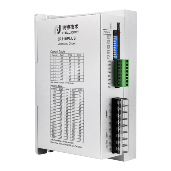
3R110 Plus User Manual 4. The setting of DIP switches and operating parameters The setting of current Standby current The setting of pulse per revolution Filtering Pulse mode 4.1 The setting of current Sine peak A Remarks User can set 8 levels of current through debugging software 4.2 Standby current... -
Page 8: Pulse Command Filtering
3R110 Plus User Manual 3200 6400 12800 25600 1000 2000 4000 5000 8000 10000 20000 25000 4.4 Pulse command filtering The driver has a built-in pulse command smoothing function, which can make the motor start more stable. SW9 = ON, enable pulse command filtering SW9 = OFF, disable pulse command filtering The default command filter time is 512*61us=31ms Command filtering can smooth the motor movement, but also introduces lag. -
Page 9: The Setting Of Pulse Mode
3R110 Plus User Manual 4.5 The setting of pulse mode SW10 is used to set the form of the driver receiving pulse. SW10 = OFF, pulse + direction mode SW10 = ON, CW+CCW double pulse mode 5. Driver working status LED indication Driver status LED status Driver not enabled... -
Page 10: Communication Control Mode
3R110 Plus User Manual 7.1 Communication control mode In this mode, the user can make the motor run the specified pulse stroke or jog operation by communicating the given operation command. In internal pulse mode, the motor is controlled by register 18 0:Waiting state. -
Page 11: Jog Control Mode
7.1.2 Jog control mode 3R110Plus has the function of controlling the jog operation of the motor through communication.The specific modes and parameters to be set are as follows (register addresses are not specified or... -
Page 12: Io Control: Start And Stop + Direction
3R110 Plus User Manual (3) Set the motion parameters: Address Unit Parameter Description Acceleration of jog motion R/S^2 Deceleration of jog motion R/S^2 Speed of jog motion Emergency stop deceleration R/S^2 (4) Communication given operation command: Start jog movement by writing values 3 (continuous forward rotation) and 4 (continuous reverse rotation) to register 18.(For details on this register, please see "Drive Control Mode"... -
Page 13: Io Control: Forward + Reverse
3R110 Plus User Manual (3)IO settings: (4)This mode is for the speed defined by the speed table, selected by SW5, 6, 7, 8. (5)Set the motion parameters, you can modify the acceleration, deceleration 7.3 IO Control: Forward + Reverse Same as 7.2, only need to change (2) to: 3 – IO speed control: forward + reverse. szruitech.com... -
Page 14: Common Faults And Troubleshooting
3R110 Plus User Manual 8. Common faults and troubleshooting Phenomenon Possible situations Solutions Check the power supply circuit for normal Power indicator is off power supply The motor rotor is locked but the Pulse signal is weak; increase the signal motor does not work current to 7-16mA Motor does... - Page 15 3R110 Plus User Manual 9.3 Maintenance process For maintenance of products, please follow the procedures shown below: (1) Contact our customer service staff to get the rework permission. (2) The written document of the Driver failure phenomenon is attached to the goods, as well as the contact information and mailing methods of the sender.
Need help?
Do you have a question about the 3R110PLUS and is the answer not in the manual?
Questions and answers