
Related Manuals for UNICORECOMM UB4B0


Summary of Contents for UNICORECOMM UB4B0
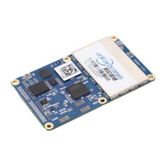
- Page 1 UB4B0 GPS/BDS/GLONASS/Galileo All-Constellation Multi-Frequency High Precision Board...
- Page 3 Foreword This <User Manual> offers you information in the features of the hardware, the installation, specification and use of Unicore UB4B0 product. For the generic version of this manual, please refer to different part of the manual according to your purchased product configuration, concerning CORS, RTK and Heading.
-
Page 4: Table Of Contents
Content 1 OVERVIEW ..........3 ............................ 4 EATURES 2 INSTALLATION ........... 4 .......................... 4 ACKAGE NSPECTION ESD P ..........................5 ROTECTION ..........................6 OARD VERVIEW ........................... 7 NSTALLATION UIDE 3 PC UTILITY CONFIGURATION(UPRECISE) ....12 ............................12 VERVIEW ..........................13 PERATION TEPS 4 FIRMWARE UPDATE(WINCONFIG)... -
Page 5: Overview
ALL-Constellation Multi-Frequency High Precision OEM Board. The UB4B0 can provide reliable centimeter-level accuracy and high accuracy heading output at high update rate .UB4B0 employ the new generation all-constellation multi-core high precision SoC chip, Nebulas-II (432 channel tracking), based on mature base line chip (XINGYUN), 55nm low power consumption,built in broadband ADC and anti-interference unit,integrated two... -
Page 6: Key Features
This section contains the list of the product package and the details of product installation. 2.1 Package Inspection Please check the contents of the package carefully after receiving the package of UB4B0: UB4B0 board and EVK suite (or evaluation board) (or enclosure) ... -
Page 7: Esd Protection
MMCX antenna cable Cross serial Port cable 2.2 ESD Protection A lot of components onUB4B0 susceptible to electrostatic damage, which affects IC circuits and other components. Please follow the instructions below for ESD protection before open the plastic package: ... -
Page 8: Board Overview
Nebulas-II (UC4C0) is Unicore’s new generation high precision GNSS SoC with 55nm low power design, supports up to 12 digital intermediate frequency or 8 analog intermediate frequency signals, which can track 12 navigation signals with 432 channels. 3. MEMS* This is an optional function. If selecting GNSS+INS,UB4B0 is integrated on-board... -
Page 9: Installation Guide
Power input, data communication port, pulse trigger, LED etc. 2.4 Installation Guide UB4B0 is delivered as a board, users can flexibly assemble according to the scenario and the market need. Figure below shows the typical installation of UB4B0 with evaluation kit... - Page 10 UB4B0 User Manual Fig 2-2 UB4B0 installation For efficient installation, please get prepared for the following items before installation: UB4B0 EVK suite (or evaluation board) (or enclosure) User manual Command manual UPrecise software (CD attached) Qualified antenna ...
- Page 11 , and so on).. Fig 2-3 installation step 1 Select a GNSS antenna with appropriate gain, and mount it in a open sky area. Connect the antenna to J1 MMCX port of UB4B0 via coaxial RF cable. Only for manufactory test...
- Page 12 UB4B0 User Manual Fig 2-4 installation step 2 The RF connector of the board is MMCX, please select the appropriate cable. The signal gain to board RF connector should be within 25 to 35dB. The Antenna connector provides 5VDC antenna 。...
- Page 13 Fig 2-6 installation step 3 Connect a 12V adapter with the EVK power input, and switch on to power the device Fig 2-7 installation step 4...
-
Page 14: Pc Utility Configuration(Uprecise
UB4B0 User Manual Start UPRECISE on the PC Refer to UPRECISE online help to send commands or log data for the receiver Note: In case the card has not been in use for a long time, or the distance from last time used location is above 1000Km, a slower fix may occur. -
Page 15: Operation Steps
Sending commands to the Receiver The trajectory view for displaying the present point and the past point of the Receiver Upgrading the firmware TTFF test Fig 3-1 UPrecise Overview 3.2 Operation Steps 1. Follow the tutorial to install the board, and turn on the EVK switch 2. -
Page 16: Firmware Update(Winconfig
6. Configure or type commands according to requirements in various UPrecise views 4 Firmware Update(WinConfig) WinConfig(in the attached CD) software is used for the remote update of UB4B0, please follow the steps below to install the software: During the firmware update of the board, please stop all the operations to... - Page 17 Step 1: Click the program icon to run the software: Figure 4-1 WinConfig Welcome Interface Step 2: Click “Next” to browse the firmware update package: Figure 4-2 Select Firmware Update Package...
- Page 18 UB4B0 User Manual Step 3: Click “Next” to display the communication type: Figure 4-3 Select Communication Type Step 4:Select the communication type as through Serial Port(COM), click “Next” to configure: Figure 4-4 Serial Port Communication Configuration...
- Page 19 Please use COM1 to update firmware. Step 5: After the configuration of the COM port, click “Next” to prompt the configuration summary dialog: Figure 4-5 Serial Port Upgrade Configuration Summary Step 6:Check the summary to make sure the receiver is correctly configured, then click “Finish”...
- Page 20 UB4B0 User Manual Figure 4-6 Firmware Upgrade Window Step 7: Click“Upgrade” to start the firmware upgrading process: Figure 4-7 Serial Port Upgrade Success The "Upgrade" button is gray and can’t be clicked while the receiver is in the upgrading process, unless the upgrade is complete, or an error occurs during the...
- Page 21 Step 8: Check the firmware upgrading process is finished successfully:...
-
Page 22: Hardware Interface
UB4B0 User Manual 5 Hardware Interface This chapter is a brief introduction about UB4B0 receiver I/O port and Electrical Characteristics, please connect correctly in case unnecessary damage 5.1 Power Input Index Description Acceptable velocity Input range 3.3V +5%/-3% Note: Please avoid switching power supply frequently, it is recommended that the switching interval is greater than 5s. -
Page 23: Serial Port Access
Note: When configuring the serial port, make sure that the baud rate matches the data amount and confirm that the baud rate set by your hardware device is supported. Otherwise, an exception may occur. 5.5 Pin Function UB4B0 provides dual row 2x12 pin(2.0mm pitch)as main interface. As following: Signal Type... - Page 24 UB4B0 User Manual Signal Type Description Note Power Supply Voltage,+3.3V +5%/–3% Supply Voltage,+3.3V +5%/–3% Power Rx3 or Event2 Input External Event 2 Default: LVTTL COM3 Receive Data Event1 Input External Event 1 LVTTL LVTTL , Low Level ERROR Output Error Detected LED effective LVTTL ,...
- Page 25 Signal Type Description Note USB D (+) Input/Output USB D+ Ground Ground In addition,UB4B0 provides a 10/100M Ethernet interface、CAN、Odometer interface, with dual row 2x8 pin(2.0mm pitch). As following: Signal Function Description ETH_RD- Negative electrode of Ethernet Connect to RD- receiving data, Differential pair.
- Page 26 UB4B0 User Manual ETH_TD- Negative electrode of Ethernet Connect to TD- receiving data, Differential pair. CENT_TD Ethernet interface Transformer Connect to TD Center center send taps ETH_LINK Ethernet interface connect indicator light LOW Level:connection building; High Level:ununited; ETH_SPD Ethernet interface network speed indicator LOW Level:100Mbps...
-
Page 27: Appendix I Mechanical Drawing
Appendix I Mechanical drawing J1: MMCX female,GNSS antenna interface... -
Page 28: Appendix Ii Technical Specifications
UB4B0 User Manual J2: MMCX female,10M external clock interface J3: 2x12 dual row pin(2.0mm pitch) J4: 2x8 dual row pin(2.0mm pitch) Appendix II Technical Specifications Performance Specifications Channels 432 channels, based on Initialization <10s( Typical) time Nebulas-II SoC chip Frequency... - Page 29 Phase accuracy(RMS) NTRIP、HTTP、 B2/L2P(Y) /E5b 10cm 10cm 10cm 10cm Network code Protocol B2/L2/E5b Carrier Phase B3/L5/E5a code 10cm 10cm 10cm B3/L5/E5a Carrier Phase Physical Specifications 100×60×11.4 mm Dimension Weight -40℃~+85℃ Work temperature -55℃~+95℃ Storage temperature Humidity 95% non-condensing I/O Connectors 2x12 Pin 2x8 Pin Antenna Input...
- Page 30 UB4B0 User Manual 100mV p-p(max) Voltage Ripple Power Dissipation 2.8W (typical) Functional Ports 1x UART (RS-232),2 x UART(LV-TTL), 460800bps Serial 1x LAN,10/100M Internet access 1PPS interface LV-TTL...
Need help?
Do you have a question about the UB4B0 and is the answer not in the manual?
Questions and answers