Table of Contents

Related Manuals for UNICORECOMM UB4B0


Summary of Contents for UNICORECOMM UB4B0
- Page 1 INSTALLATION AND OPERATION USER MANUAL WWW.UNICORECOMM.COM UB4B0 GPS/BDS/GLONASS/Galileo ALL-Constellation Multi-Frequency High Precision Board Copyright© 2009-2020, Unicore Communications, Inc. Data subject to change without notice.
- Page 2 Revision History Version Revision History Date Ver. 1.0 First release Aug. 2017 Ver. 1.1 Update the Dimension of UB4B0 Feb.2019 R1.3 Revise mechanical spec/add HW design 2019-08-28 notes/remove MEMS info R1.4 Add the shield dimension 2019-10-12 R2.0 Align the installation diagram with HW 2020-02-20 ver3.1...
- Page 3 Foreword This <User Manual> offers you information in the features of the hardware, the installation, specification and use of UNICORECOMM UB4B0 product. For the generic version of this manual, please refer to different part of the manual according to your purchased product configuration, concerning CORS, RTK and Heading.
-
Page 4: Table Of Contents
Content 1 OVERVIEW ........... 1 ........................1 EATURES 2 HARDWARE DESIGN IN CONSIDERATIONS ..... 2 3 INSTALLATION ........2 ......................2 ACKAGE NSPECTION ........................3 ESD P ROTECTION ........................3 OARD VERVIEW ....................... 4 NSTALLATION UIDE 4 LED INDICATORS ........8 5 PC UTILITY CONFIGURATION(UPRECISE)... -
Page 5: Overview
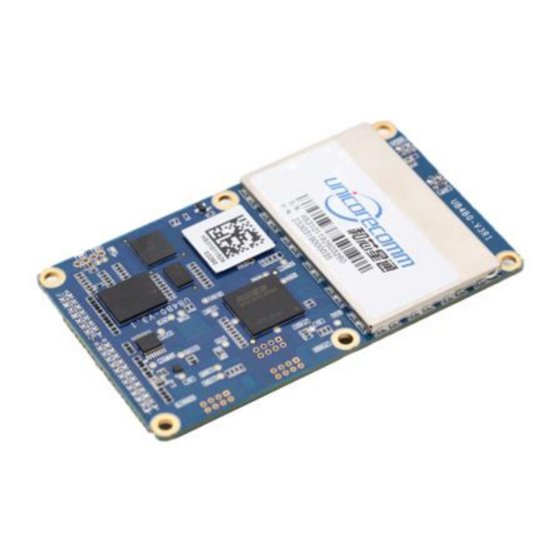
ALL-Constellation Multi-Frequency High Precision OEM Board. The UB4B0 can provide reliable centimeter-level accuracy and high accuracy heading output at high update rate .UB4B0 employ the new generation all-constellation multi-core high precision SoC chip, NebulasII (432 channel tracking), based on mature base line chip (XINGYUN), 55nm low power consumption,... -
Page 6: Hardware Design In Considerations
This section contains the list of the product package and the details of product installation. 3.1 Package Inspection Please check the contents of the package carefully after receiving the package of UB4B0: UB4B0 board and EVK suite (or evaluation board) (or enclosure) User manual (CD attached) ... -
Page 7: Esd Protection
MMCX antenna cable Cross serial Port cable 3.2 ESD Protection A lot of components onUB4B0 susceptible to electrostatic damage, which affects IC circuits and other components. Please follow the instructions below for ESD protection before open the plastic package: ... -
Page 8: Installation Guide
Power input, data communication port, pulse trigger, LED etc. 3.4 Installation Guide UB4B0 is delivered as a board, users can flexibly assemble according to the scenario and the market need. Figure below shows the typical installation of UB4B0 with evaluation kit (EVK), users can also use other enclosures to install receiver, using the same method. - Page 9 After the above preparation is made, please follow the steps below to install: : Following the steps below to install the device: Align UB4B0 positioning holes and pins with EVK, and fix UB4B0 in the EVK. EVK provides power supply and standard communication interface for the board, to...
- Page 10 Figure 3-3 Installation Step 1 Select a GNSS antenna with appropriate gain, and mount it in an open sky area. Connect the antenna to J1 MMCX port of UB4B0 via coaxial RF cable. Figure 3-4 Installation Step 2 NOTE: The RF connector of the board is MMCX, please select the appropriate cable.
- Page 11 Figure 3-5 Installation Step 3 Figure 3-6 Installation Step 3 Connect a 12V adapter with the EVK power input, and switch on to power the device...
-
Page 12: Led Indicators
15 minutes to collect new ephemeris and Almanac information. 4 LED Indicators There is a double color LED indicator on UB4B0, which can indicate the working status of the board. Status... - Page 13 Status Green Remark Blank Time interval between two Status Switch Blank 1s positioning status Red Fast Flash, abnormal status abnormal 0.25s other than 1-5 Switch into other status after Stead Power on starting up. 1. For normal status, the indicating sequence is: power on->status switch->insufficient satellites->...
-
Page 14: Pc Utility Configuration(Uprecise
Manual 5 PC Utility Configuration(UPrecise) 5.1 Overview UB4B0 Unicore UPRECISE (Control and Display Tool) provides a user-friendly graphical interface to control and display the operation of your receiver. User can access the functionality and information just through several clicks. The following features are included in UPRECISE:... -
Page 15: Operation Steps
Figure 5-1 UPrecise Overview 5.2 Operation Steps 1. Follow the tutorial to install the board, and turn on the EVK switch 2. Click file - > connect the serial port, set the baud rate, the default baud rate is 115200bps Figure 5-2 Configure Baud Rate 3. -
Page 16: Firmware Update(Winconfig
6. Configure or type commands according to requirements in various UPrecise views 6 Firmware Update(WinConfig) WinConfig (in the attached CD) software is used for the remote update of UB4B0, please follow the steps below to install the software: During the firmware update of the board, please stop all the operations to the device, including the cutoff of the power supply. - Page 17 Figure 6-1 WinConfig Welcome Interface Step 2: Click “Next” to browse the firmware update package: Figure 6-2 Select Firmware Update Package Step 3: Click “Next” to display the communication type:...
- Page 18 UB4B0 User Manual Figure 6-3 Select Communication Type Step 4:Select the communication type as through Serial Port(COM), click “Next” to configure: Figure 6-4 Serial Port Communication Configuration Please use COM1 to update firmware. Step 5: After the configuration of the COM port, click “Next” to prompt the configuration...
- Page 19 Figure 6-5 Serial Port Upgrade Configuration Summary Step 6:Check the summary to make sure the receiver is correctly configured, then click “Finish” to prompt the Upgrade window: Figure 6-6 Firmware Upgrade Window Step 7: Click“Upgrade” to start the firmware upgrading process:...
-
Page 20: Hardware Interface
Step 8: Check the firmware upgrading process is finished successfully. 7 Hardware Interface This chapter is a brief introduction about UB4B0 receiver I/O port and Electrical Characteristics, please connect correctly in case unnecessary damage 7.1 Power Input Index... -
Page 21: External Clock Input
Note: When configuring the serial port, make sure that the baud rate matches the data amount and confirm that the baud rate set by your hardware device is supported. Otherwise, an exception may occur. 7.5 Pin Function UB4B0 provides dual row 2x12 pin(2.0mm pitch)as main interface. As following:... - Page 22 UB4B0 User Manual Signal Type Description Note Ground Ground Reference RTK LED Output RTK LED LVTTL, High level effective Reserved Output Time Mark Output LVTTL Power Supply Voltage, +3.3V +5%/–3% Power Supply Voltage, +3.3V +5%/–3% Rx3 or Event2 Input External Event 2 Default:...
- Page 23 Input/Output USB D - USB D (+) Input/Output USB D+ Ground Ground In addition, UB4B0 provides a 10/100M Ethernet interface, CAN, Odometer interface, with dual row 2x8 pin (2.0mm pitch). As following: Signal Function Description ETH_RD- Negative electrode of Ethernet Connect to RD- receiving data, Differential pair.
- Page 24 UB4B0 User Manual Signal Function Description light LOW Level: connection building; High Level: ununited; ETH_SPD Ethernet interface network speed indicator LOW Level: 100Mbps High Level: 10Mbps Ground CAN_TX CAN bus transmit data CAN_RX CAN bus receive data Reserved Reserved Reserved...
-
Page 25: Appendix I Mechanical Drawing
Appendix I Mechanical drawing Parameter Value Tolerance Length 100mm -0.2mm +0.5mm Width 60mm ± 0.2mm 1.6mm ± 10% Height (PCB) RF Connector 4.5mm ± 0.2mm Shield 3.1mm ± 0.2mm Pin Height 5.9mm ± 0.2mm... - Page 26 UB4B0 User Manual J1: MMCX female, GNSS antenna interface J2: MMCX female, 10M external clock interface J3: 2x12 dual row pin (2.0mm pitch) J4: 2x8 dual row pin (2.0mm pitch)
-
Page 27: Appendix Ii Technical Specifications
Appendix II Technical Specifications Performance Specifications Channels 432 channels, based on Cold start <40s NebulasII SoC chip Frequency BDS B1I/B2I/B3I/B1a/B1C Hot start <10s GPS L1/L2/L5 GLONASS L1/L2 Galileo E1/E5a/E5b QZSS L1/L2/L5 re-acquisition <1s Initialization <10s (Typical) time Single point Horizontal: 1.5m Initialization >... - Page 28 UB4B0 User Manual Physical Specifications 100×60×11.4 mm Dimension Weight -40℃~+85℃ Work temperature Storage temperature -40℃~+85℃ Humidity 95% non-condensing I/O Connectors 2x12 Pin 2x8 Pin Antenna•Input MMCX External clock input MMCX Vibration GJB150.16-2009, MIL-STD-810 Shock GJB150.18-2009, MIL-STD-810 Electrical Specifications 3.0~3.3VDC 4.75~5.10V, 0~100 mA Voltage Ripple 100mV p-p(max)...
- Page 29 和芯星通科技(北京)有限公司 Unicore Communications, Inc. 北京市海淀区丰贤东路7号北斗星通大厦三层 F3, No.7, Fengxian East Road, Haidian, Beijing, P.R.China, 100094 www.unicorecomm.com Phone: 86-10-69939800 Fax: 86-10-69939888 info@unicorecomm.com www.unicorecomm.com...
Need help?
Do you have a question about the UB4B0 and is the answer not in the manual?
Questions and answers