
Related Manuals for UNICORECOMM UB4B0


Summary of Contents for UNICORECOMM UB4B0
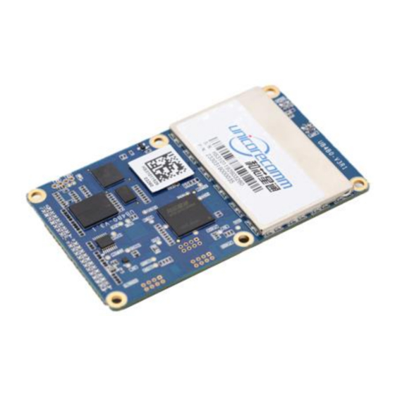
- Page 1 INSTALLATION AND OPERATION USER MANUAL WWW.UNICORECOMM.COM UB4B0 ALL-constellation GNSS High Precision Board Copyright© 2009-2021, Unicore Communications, Inc. Data subject to change without notice.
- Page 2 Revision History Version Revision History Date Ver. 1.0 First release Aug. 2017 Ver. 1.1 Update the Dimension of UB4B0 Feb.2019 R1.3 Revise mechanical spec/add HW design notes/remove 2019-08-28 MEMS info R1.4 Add the shield dimension 2019-10-12 R2.0 Align the installation diagram with HW ver3.1 2020-02-20 R2.1...
- Page 3 Foreword This <User Manual> offers you information in the features of the hardware, the installation, specification and use of UNICORECOMM UB4B0 product. This manual is a generic version. Please refer to the appropriate part of the manual according to your purchased product configuration, concerning CORS, RTK and Heading.
-
Page 4: Table Of Contents
Contents 1 OVERVIEW ........... 1 ........................1 EATURES 2 HARDWARE DESIGN IN CONSIDERATIONS ..... 2 3 INSTALLATION ........2 ......................2 ACKAGE NSPECTION ........................3 ESD P ROTECTION ........................3 OARD VERVIEW ....................... 4 NSTALLATION UIDE 4 LED INDICATORS ........8 5 PC UTILITY CONFIGURATION (UPRECISE) .... -
Page 5: Overview
UB4B0 provides millimeter-level carrier-phase observation data and centimeter-level RTK position output, supports advanced multi-path mitigation and low angle tracking; UB4B0 is suitable for high precision surveying and mapping application, especially for geodetic surveying, engineering survey, deformation monitoring, mechanical control, meteorological monitoring, precision agriculture, continuous operation reference station (CORS), advanced instantaneous RTK and long-distance RTK, etc. -
Page 6: Hardware Design In Considerations
This section contains the list of the product package and the details of product installation. 3.1 Package Inspection Please check the contents of the package carefully after receiving the package of UB4B0: UB4B0 board and EVK suite (or evaluation board) (or enclosure) ... -
Page 7: Esd Protection
3.2 ESD Protection A lot of components on UB4B0 are susceptible to electrostatic damage, which affects IC circuits and other components. Please follow the instructions below for ESD protection before open the plastic package: Electrostatic discharge (ESD) can damage components. Please use an anti-static work bench, a conductive foam pad, and at the same time, wearing an anti-static wrist strap. -
Page 8: Installation Guide
12 digital intermediate frequency or 8 analog intermediate frequency signals, which can track 12 navigation signals with 432 channels. 3. 1PPS UB4B0 provides 1 PPS with adjustable pulse width and polarity and 1 output pulse width. 4. Event UB4B0 provides 1 Event Mark Input. - Page 9 After the above preparation is made, please follow the steps below to install: Following the steps below to install the device: Align UB4B0 positioning holes and pins with EVK, and fix UB4B0 on the EVK. EVK provides power supply and standard communication interface for the board, to...
- Page 10 Figure 3-3 Installation Step 1 Select a GNSS antenna with appropriate gain, and mount it in an open sky area. Connect the antenna to J1 MMCX port of UB4B0 via coaxial RF cable. Antenna RF input Figure 3-4 Installation Step 2 NOTE: The RF connector on the board is MMCX, please select the appropriate cable.
- Page 11 Figure 3-5 Installation Step 3 Figure 3-6 Installation Step 3 Connect a 12V adapter with the EVK power input, and switch on to power the device...
-
Page 12: Led Indicators
15 minutes to collect new ephemeris and Almanac information. 4 LED Indicators There is a double color LED indicator on UB4B0, which can indicate the working status of the board. Status... -
Page 13: Pc Utility Configuration (Uprecise)
-> abnormal Figure 4-1 LED Indicators 5 PC Utility Configuration (UPrecise) 5.1 Overview UB4B0 Unicore UPRECISE (Control and Display Tool) provides a user-friendly graphical interface to control and display the operation of your receiver. User can access the... - Page 14 UB4B0 User Manual functionality and information just through several clicks. The following features are included in UPRECISE: Connecting the receiver, configuring the baud rate Graphic window for displaying Position of satellite, PRN, and Signal/Noise Ratio (Constellation View) Displaying the historical and present Trajectory of the receiver, as well as the position, velocity, and time (Trajectory View) ...
-
Page 15: Operation Steps
5.2 Operation Steps 1. Follow the tutorial to install the board, and turn on the EVK switch 2. Click file -> connect the serial port, set the baud rate, the default baud rate is 115200bps Figure 5-2 Configure Baud Rate 3. -
Page 16: Firmware Update (Winconfig)
6. Configure or type commands according to requirements in various UPrecise views 6 Firmware Update (WinConfig) WinConfig (in the attached CD) software is used for the remote update of UB4B0, please follow the steps below to install the software: During the firmware update of the board, please stop all the operations to the device, including the cutoff of the power supply. - Page 17 Figure 6-2 Select Firmware Update Package Step 3: Click “Next” to display the communication type: Figure 6-3 Select Communication Type Step 4:Select the communication type as through Serial Port (COM), click “Next” to configure:...
- Page 18 UB4B0 User Manual Figure 6-4 Serial Port Communication Configuration Please use COM1 to update firmware. Step 5: After the configuration of the COM port, click “Next” to prompt the configuration summary dialog: Figure 6-5 Serial Port Upgrade Configuration Summary Step 6:Check the summary to make sure the receiver is correctly configured, then click...
- Page 19 Figure 6-6 Firmware Upgrade Window Step 7: Click “Upgrade” to start the firmware upgrading process: Figure 6-7 Serial Port Upgrade Success The "Upgrade" button is gray and can’t be clicked while the receiver is in the upgrading process, unless the upgrade is complete, or an error occurs during the upgrade process.
-
Page 20: Hardware Interface
UB4B0 User Manual 7 Hardware Interface This chapter is a brief introduction about UB4B0 receiver I/O port and Electrical Characteristics, please connect correctly to avoid unnecessary damage. 7.1 Absolute Maximum Rating Item Unit Power Supply (VCC) -0.3 VCC Ripple (Rated Max.) -
Page 21: Pin Function
7.6 Pin Function UB4B0 provides dual row 2x12 pin (2.0mm pitch) as main interface. As follows: Signal Type Description Note Ground Ground Reference RTK LED Output RTK LED LVTTL, high level effective Reserved Output Time Mark Output LVTTL +5%/–3% Power Supply Voltage, +3.3V... - Page 22 Input/Output USB D - USB D (+) Input/Output USB D+ Ground Ground In addition, UB4B0 provides a 10/100M Ethernet interface, CAN, Odometer interface, with dual row 2x8 pin (2.0mm pitch). As follows: Signal Function Description ETH_RD- Negative electrode of Ethernet Connect to RD- receiving data, Differential pair.
- Page 23 Signal Function Description ETH_SPD Ethernet interface network speed indicator LOW Level: 100Mbps High Level: 10Mbps Ground CAN_TX CAN bus transmit data CAN_RX CAN bus receive data Reserved Reserved Reserved Ground SPEED Odometer velocity Input Odometer direction message Input Ground This will be supported in the future release...
-
Page 24: Appendix I Mechanical Drawing
UB4B0 User Manual Appendix I Mechanical drawing Parameter Value Tolerance Length 100mm -0.2mm +0.5mm Width 60mm ±0.2mm Height (PCB) 1.6mm ±10% RF Connector 4.5mm ±0.2mm Shield 3.1mm ±0.2mm Pin Height 5.9mm ±0.2mm... - Page 25 J1: MMCX female, GNSS antenna interface J2: MMCX female, 10M external clock interface J3: 2x12 dual row pin (2.0mm pitch) J4: 2x8 dual row pin (2.0mm pitch)
-
Page 26: Appendix Ii Technical Specifications
UB4B0 User Manual Appendix II Technical Specifications Performance Specifications 432 channels, based on Channels Cold Start <40s NebulasII SoC Hot Start <10s BDS B1I/B2I/B3I/B1C/B2a/B2b* GPS L1/L2C/L2P(Y)/L5 Re-Acquisition <1s Frequency GLONASS L1/L2 RTK Initialization Galileo E1/E5a/E5b <5s (Typical) Time QZSS L1/L2/L5... - Page 27 Physical Specifications Dimension 100×60×11.4 mm Weight -40℃~+85℃ Operating Temperature Storage Temperature -40℃~+85℃ Humidity 95% non-condensing I/O Connectors 2x12 Pin 2x8 Pin Antenna Input MMCX External Clock Input MMCX Vibration GJB150.16-2009, MIL-STD-810 Shock GJB150.18-2009, MIL-STD-810 Electrical Specifications 3.0~3.3VDC 4.75~5.10V, 0~100 mA 100mV p-p(max)...
- Page 28 和芯星通科技(北京)有限公司 Unicore Communications, Inc. 北京市海淀区丰贤东路7号北斗星通大厦三层 F3, No.7, Fengxian East Road, Haidian, Beijing, P.R.China, 100094 www.unicorecomm.com Phone: 86-10-69939800 Fax: 86-10-69939888 info@unicorecomm.com www.unicorecomm.com...
Need help?
Do you have a question about the UB4B0 and is the answer not in the manual?
Questions and answers