
Related Manuals for Makita GTR01


Summary of Contents for Makita GTR01
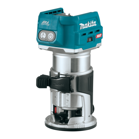
- Page 1 INSTRUCTION MANUAL MANUAL DE INSTRUCCIONES Cordless Trimmer Recortadora Inalámbrica GTR01 IMPORTANT: Read Before Using. IMPORTANTE: Lea antes de usar.
-
Page 2: Specifications
ENGLISH (Original instructions) SPECIFICATIONS Model: GTR01 Collet chuck capacity 1/4" No load speed 10,000 - 31,000/min Overall height with BL4025 245 mm (9-5/8″) with BL4040 251 mm (9-7/8″) Rated voltage D.C. 36 V - 40 V max Net weight 2.2 - 2.5 kg (4.9 - 5.5 lbs) •... - Page 3 Use personal protective equipment. Always Keep cutting tools sharp and clean. Properly wear eye protection. Protective equipment such maintained cutting tools with sharp cutting edges as dust mask, non-skid safety shoes, hard hat, or are less likely to bind and are easier to control. hearing protection used for appropriate conditions Use the power tool, accessories and tool bits will reduce personal injuries.
- Page 4 Cordless trimmer safety warnings Symbols Use clamps or another practical way to secure The followings show the symbols used for tool. and support the workpiece to a stable platform. Holding the work by your hand or against the body volts leaves it unstable and may lead to loss of control.
- Page 5 17. Do not remove the wireless unit from the slot causing fires, personal injury and damage. It will while the power is being supplied to the tool. also void the Makita warranty for the Makita tool and Doing so may cause a malfunction of the wireless unit. charger.
-
Page 6: Functional Description
Indicating the remaining battery FUNCTIONAL capacity DESCRIPTION Press the check button on the battery cartridge to indi- cate the remaining battery capacity. The indicator lamps CAUTION: Always be sure that the tool is light up for a few seconds. switched off and the battery cartridge is removed before adjusting or checking function on the tool. -
Page 7: Overheat Protection
Charge the battery(ies) or replace it/them with recharged battery(ies). Let the tool and battery(ies) cool down. If no improvement can be found by restoring protection system, then contact your local Makita Service Center. Switch action To turn on the tool, press the lock/unlock button. The Fig.4 tool turns into the standby mode. -
Page 8: Electronic Function
If the tool consistently fails to stop the trimmer bit after the switch is turned off, have the tool ser- viced at a Makita service center. ASSEMBLY CAUTION: Always be sure that the tool is switched off and the battery cartridge is removed before carrying out any work on the tool. - Page 9 Attach the dust nozzle to the trimmer base, and Installing or removing the trimmer then tighten the thumb screw. base Open the lock lever of the trimmer base, then insert the tool into the trimmer base aligning the groove on the tool with the protrusion on the trimmer base. Close the lock lever.
- Page 10 Remove the collet nut and the collet cone. Installing or removing the tilt base Optional accessory Open the lock lever of the tilt base, then insert the tool into the tilt base aligning the groove on the tool with the protrusion on the tilt base. Close the lock lever.
- Page 11 Open the lock lever of the offset base, then attach Attach the base plate by tightening the screws. the offset base to the tool. Fig.22 ► 1. Base plate Insert the collet cone and the trimmer bit into the Fig.19 offset base, and then tighten the collet nut.
- Page 12 Installing or removing the parallel To remove the base, follow the installation procedure in reverse. ruler on the plunge base NOTE: You can also mount the belt to the pulley with- Optional accessory out removing the base plate as shown in the figure. Insert the guide bars into the holes in the plunge base, and then tighten the wing bolts.
-
Page 13: Operation
Adjusting cutting depth with the OPERATION plunge base Adjusting cutting depth Optional accessory Place the tool on the flat surface. To adjust the cutting depth, open the lock lever, then Select the stopper screw by rotating the stopper move the tool base up or down by turning the adjusting base. - Page 14 Press down the stopper pole while pressing the To perform fine adjustment of the cutting depth, feed button until it contacts the stopper screw. turn the dial on the stopper pole so that it indicates "0". Fig.35 Fig.38 ► 1. Stopper pole 2. Stopper screw 3. Feed button ►...
- Page 15 Release the fixing lever. When using the trimmer shoe, the straight guide, or the trimmer guide, be sure to keep it on the right side in the feed direction. This will help to keep it flush with the side of the workpiece. Fig.41 ►...
- Page 16 Loosen the wing nut on the straight guide and Using the straight guide for circular adjust the distance between the trimmer bit and the work straight guide. At the desired distance, tighten the wing nut. For circular work, assemble the straight guide as shown in the figures.
- Page 17 Align the center hole in the straight guide with the Place the tool on the templet and move the tool center of the circle to be cut. Drive a nail less than 6 so that the templet guide slides along the side of the mm (1/4") in diameter into the center hole to secure templet.
- Page 18 Loosen the clamp screw, then install the trimmer Using the tool with the tilt base guide on the trimmer base, and then tighten the clamp screw. The tilt base is used for trimming the edge of laminate sheet or similar materials. The tilt base is convenient for chamfering.
- Page 19 Attach the offset base plate to the trimmer base by Using the tool with the offset base tightening the screws. Attach the grip attachment and the bar type grip to The offset base is used for trimming the edge of lami- the offset base plate by tightening the screws.
- Page 20 Using the templet guide Using the tool with the plunge base Optional accessory Always hold the grips firmly with both hands during opera- Loosen the screws on the base and remove them. tion. Operate the tool in the same way as the trimmer base. Place the templet guide on the base, and then tighten the screws.
- Page 21 If the distance (A) between the side of the workpiece WIRELESS ACTIVATION and the cutting position is too wide for the parallel ruler, or if the side of the workpiece is not straight, the parallel FUNCTION ruler cannot be used. In this case, firmly clamp a straight board to the work- piece and use it as a guide against the plunge base.
- Page 22 Open the lid on the tool as shown in the figure. Tool registration for the vacuum cleaner NOTE: A Makita vacuum cleaner supporting the wireless activation function is required for the tool registration. NOTE: Finish installing the wireless unit to the tool before starting the tool registration.
- Page 23 Push the wireless activation button on the tool NOTE: The wireless activation lamps finish blinking briefly. The wireless activation lamp will blink in blue. in green after 20 seconds elapsed. Press the wireless activation button on the tool while the wireless acti- vation lamp on the cleaner is blinking.
- Page 24 Description of the wireless activation lamp status Fig.82 ► 1. Wireless activation lamp The wireless activation lamp shows the status of the wireless activation function. Refer to the table below for the meaning of the lamp status. Status Wireless activation lamp Description Color Duration...
- Page 25 Cancelling tool registration for the vacuum cleaner Perform the following procedure when cancelling the tool registration for the vacuum cleaner. Install the batteries to the vacuum cleaner and the tool. Set the stand-by switch on the vacuum cleaner to "AUTO". Fig.83 ►...
- Page 26 Before asking for repairs, conduct your own inspection first. If you find a problem that is not explained in the manual, do not attempt to dismantle the tool. Instead, ask Makita Authorized Service Centers, always using Makita replace- ment parts for repairs.
-
Page 27: Maintenance
Discoloration, deformation or cracks may result. To maintain product SAFETY and RELIABILITY, repairs, any other maintenance or adjustment should be performed by Makita Authorized or Factory Service Fig.86 Centers, always using Makita replacement parts. TRIMMER BITS 1/4″... - Page 28 Drill point flush trimming bit Corner rounding bit Fig.88 Fig.90 1/4″ 1/4″ 1/4″ Unit:mm Unit:mm Drill point double flush trimming bit Chamfering bit Fig.89 Fig.91 θ 30° 1/4″ 45° 60° Unit:mm 1/4″ 30° 1/4″ 45° 1/4″ 60° Unit:mm 28 ENGLISH...
- Page 29 Cove beading bit Ball bearing flush trimming bit Fig.92 Fig.94 1/4″ 1/4″ Unit:mm 1/4″ Ball bearing beading bit Unit:mm Dovetail bit θ θ θ Fig.95 Fig.93 θ 30° 1/4″ 14.5 35° 1/4″ 14.5 14.5 23° Unit:mm 1/4″ 30° 1/4″ 14.5 35°...
- Page 30 Ball bearing corner rounding bit Ball bearing cove beading bit Fig.96 Fig.98 1/4″ 1/4″ 1/4″ 1/4″ Unit:mm Unit:mm Ball bearing chamfering bit Ball bearing roman ogee bit Fig.97 Fig.99 θ 45° 60° 1/4″ 45° 1/4″ 1/4″ 60° 1/4″ Unit:mm Unit:mm 30 ENGLISH...
-
Page 31: Optional Accessories
OPTIONAL ACCESSORIES CAUTION: These accessories or attachments are recommended for use with your Makita tool specified in this manual. The use of any other accessories or attachments might present a risk of injury to persons. Only use accessory or attachment for its stated purpose. - Page 32 Accessories applicable to this trimmer The tool can be used with the following accessories for a variety of purposes. Some accessories are not available in your country. Fig.100 Trimmer base (metal) 10. Trimmer shoe Enables accurate edge works. *Use with parts of Trimmer base (resin) the trimmer guide.
- Page 33 If annexed warranty sheet is not available, refer to the warranty details set forth at below website for your respective country. United States of America: www.makitatools.com Canada: www.makita.ca Other countries: www.makita.com 33 ENGLISH...
-
Page 34: Especificaciones
ESPAÑOL (Instrucciones originales) ESPECIFICACIONES Modelo: GTR01 Capacidad del mandril de sujeción 1/4″ Velocidad sin carga 10 000 r/min - 31 000 r/min Altura total con el modelo BL4025 245 mm (9-5/8″) con el modelo BL4040 251 mm (9-7/8″) Tensión nominal 36 V - 40 V c.c. - Page 35 Cuando utilice una herramienta eléctrica en No permita que la familiaridad adquirida exteriores, utilice un cable de extensión apro- debido al uso frecuente de las herramientas piado para uso en exteriores. La utilización de haga que se sienta confiado e ignore los prin- cipios de seguridad de las herramientas.
- Page 36 Cuando vaya a utilizar esta herramienta, evite Advertencias de seguridad para la usar guantes de trabajo de tela ya que éstos recortadora inalámbrica podrían atorarse. Si los guantes de trabajo de tela llegaran a atorarse en las piezas móviles, Utilice abrazaderas o algún otro medio práctico esto podría ocasionar lesiones personales.
- Page 37 Siga las regulaciones locales relacionadas al desecho de las baterías. Instrucciones importantes de 12. Utilice las baterías únicamente con los produc- tos especificados por Makita. Instalar las baterías seguridad para el cartucho de en productos que no cumplan con los requisitos batería podría ocasionar un incendio, un calentamiento...
- Page 38 13. Cuando abra la tapa de la ranura, evite el lugar lesiones personales y daños. Asimismo, esto inva- donde el polvo y el agua puedan introducirse lidará la garantía de Makita para la herramienta y el en la ranura. Mantenga siempre la entrada de cargador Makita.
-
Page 39: Descripción Del Funcionamiento
Indicación de la capacidad restante DESCRIPCIÓN DEL de la batería FUNCIONAMIENTO Oprima el botón de verificación en el cartucho de la batería para que indique la capacidad restante de la PRECAUCIÓN: Asegúrese siempre de que la batería. Las luces indicadoras se iluminarán por algu- herramienta esté... -
Page 40: Protección Contra Sobrecarga
Deje que la herramienta y la(s) batería(s) se enfríen. Si no hay ninguna mejora al restaurar el sistema de protección, comuníquese con su centro local de servi- cio Makita. Accionamiento del interruptor Fig.4 Para encender la herramienta, oprima el botón de ►... -
Page 41: Montaje
El que se apaga el interruptor, lleve la herramienta bloqueo del eje regresará a la posición original una a un centro de servicio Makita para que le den vez que ponga en marcha la herramienta. mantenimiento. - Page 42 Cambio del cono de sujeción NOTA: Puede usar la base de la recortadora (resina) como accesorio opcional según se muestra en la figura. Al usar la base de la recortadora (resina), PRECAUCIÓN: Utilice el cono de sujeción afloje o apriete la tuerca de pulgar en lugar de abrir o del tamaño correcto para la fresa de la recorta- cerrar la palanca de bloqueo.
- Page 43 Instalación o extracción de la base descentrada Accesorio opcional Presione el bloqueo del eje y luego afloje la tuerca de sujeción. Fig.13 Para extraer la base, siga el procedimiento de instala- ción en orden inverso. PRECAUCIÓN: Cuando vaya a utilizar la herramienta con la base de la recortadora, asegú- rese de instalar la boquilla para polvo en la base de la recortadora.
- Page 44 Afloje los tornillos en la placa de base y luego Cierre la palanca de bloqueo. extraiga la placa de base. Fig.21 Fig.18 ► 1. Palanca de bloqueo ► 1. Placa de base Fije la placa de base apretando los tornillos. Abra la palanca de bloqueo de la base des- centrada y luego coloque la base descentrada a la herramienta.
- Page 45 10. Inserte la llave hexagonal en el orificio de la base Instalación o extracción de la base descentrada y luego apriete la tuerca de sujeción con la de inmersión llave. Accesorio opcional Abra la palanca de bloqueo de la base de inmer- sión, luego inserte la herramienta en la base de inmer- sión hasta el fondo, alineando la ranura en la herra- mienta con la protuberancia en la base de inmersión.
-
Page 46: Operación
Instalación o extracción de la boquilla AVISO: Si la herramienta no queda asegurada para polvo en la base de inmersión después de cerrar la palanca de bloqueo, apriete la tuerca hexagonal y luego cierre la palanca de Inserte la boquilla para polvo en la base de inmersión de bloqueo. - Page 47 Empuje la herramienta hacia abajo hasta que la Ajuste la profundidad de corte jalando hacia punta de la fresa de la recortadora toque la superficie arriba la barra de tope mientras oprime el botón de plana, y luego gire la palanca de fijación para asegurar alimentación.
- Page 48 10. Apriete la tuerca de fijación de la barra de tope. NOTA: Antes de cortar en la pieza de trabajo real, se recomienda hacer un corte de prueba. La velocidad de avance apropiada dependerá del tamaño de la fresa de la recortadora, el tipo de pieza de trabajo y la profundidad de corte.
- Page 49 Fije la guía recta a la base de la recortadora con Si la distancia (A) entre el costado de la pieza de tra- el tornillo de fijación. bajo y la posición de corte es muy ancha para la guía recta, o si el costado de la pieza de trabajo no es recto, no podrá...
- Page 50 Para cortar círculos entre 121 mm (4-3/4″) y 221 mm Uso de la guía de plantilla (8-11/16″) de radio La guía de plantilla permite repetir un corte con los patrones de plantilla mediante el uso de una plantilla. Afloje los tornillos en la placa de base y luego retire la placa de base de la base de la recortadora.
- Page 51 Afloje el tornillo de fijación y ajuste la distancia NOTA: El tamaño real del corte en la pieza de trabajo entre la fresa de la recortadora y la guía de recorte difiere ligeramente de la plantilla. La diferencia con- girando el tornillo de ajuste (1 mm (3/64″) por vuelta). siste en la distancia (X) entre la fresa de la recorta- En la distancia deseada, apriete el tornillo de fijación dora y el exterior de la guía de plantilla.
- Page 52 Uso de la herramienta con la base Uso de la herramienta con la base de inclinación descentrada La base de inclinación se utiliza para recortar el borde La base descentrada se utiliza para recortar el borde de hojas laminadas o materiales similares. de hojas laminadas o materiales similares.
- Page 53 Uso de la guía recta Fije la placa de base descentrada en la base de la recortadora apretando los tornillos. Accesorio opcional Coloque el accesorio de la empuñadura y la Instale la guía recta en el sujetador de la guía empuñadura tipo barra en la placa de base descentrada apretando la tuerca de mariposa.
- Page 54 Uso de la guía de plantilla Si la distancia (A) entre el costado de la pieza de tra- bajo y la posición de corte es muy ancha para la regla Accesorio opcional paralela, o si el costado de la pieza de trabajo no es recto, no podrá...
- Page 55 Abra la tapa en la herramienta tal como se mues- FUNCIÓN DE ACTIVACIÓN tra en la ilustración. INALÁMBRICA Lo que puede hacer con la función de activación inalámbrica La función de activación inalámbrica permite una ope- ración limpia y cómoda. Si conecta a la herramienta una aspiradora compatible, podrá...
- Page 56 NOTA: Las luces indicadoras de activación inalámbrica NOTA: Para el registro de la herramienta, se requiere terminarán parpadeando en verde después de un lapso una aspiradora Makita compatible con la función de de 20 segundos. Oprima el botón de activación inalám- activación inalámbrica.
- Page 57 Oprima el botón de activación inalámbrica en la Encienda la herramienta. Compruebe si la aspiradora herramienta durante un lapso breve. La luz indicadora funciona mientras la herramienta está en funcionamiento. de activación inalámbrica parpadeará en azul. Para detener la activación inalámbrica de la aspiradora, oprima el botón de activación inalámbrica en la herramienta.
- Page 58 Cancelación del registro de la herramienta para la aspiradora Realice el siguiente procedimiento para cancelar el registro de la herramienta para la aspiradora. Instale las baterías en la aspiradora y en la herramienta. Ajuste el interruptor de modo en espera en la aspi- radora en “AUTO”.
- Page 59 Antes de solicitar alguna reparación, primero realice una inspección por su cuenta. Si detecta algún problema que no esté explicado en el manual, no intente desensamblar la herramienta. En vez de esto, solicite la reparación a un centro de servicio autorizado de Makita, usando siempre piezas de repuesto Makita. Estado de la anomalía Causa probable (avería)
-
Page 60: Mantenimiento
Para mantener la SEGURIDAD y FIABILIDAD del pro- ducto, las reparaciones, y cualquier otra tarea de man- tenimiento o ajuste deberán ser realizadas en centros de servicio autorizados o de fábrica Makita, empleando siempre repuestos Makita. Fig.85 6 mm... - Page 61 Fresa con ranura en “U” Fresa de corte a ras con punta de taladro Fig.86 Fig.88 6 mm 6 mm 50 mm 18 mm 3 mm 6 mm 6 mm 60 mm 18 mm 28 mm 1/4″ 6 mm 50 mm 18 mm 3 mm 8 mm...
- Page 62 Fresa de redondeo de esquinas Fresa de moldura de ensenada Fig.90 Fig.92 6 mm 25 mm 9 mm 48 mm 13 mm 5 mm 8 mm 6 mm 20 mm 43 mm 8 mm 4 mm 6 mm 20 mm 8 mm 45 mm 10 mm...
- Page 63 Fresa de corte a ras con rodamiento de balines Fresa de redondeo de esquinas con rodamiento de balines Fig.94 Fig.96 6 mm 10 mm 50 mm 20 mm 6 mm 15 mm 8 mm 37 mm 7 mm 3,5 mm 3 mm 1/4″...
-
Page 64: Accesorios Opcionales
PRECAUCIÓN: Estos accesorios o aditamen- tos están recomendados para utilizarse con su herramienta Makita especificada en este manual. El empleo de cualquier otro accesorio o aditamento puede conllevar el riesgo de lesiones personales. Utilice los accesorios o aditamentos solamente para su fin establecido. - Page 65 Accesorios funcionales con esta recortadora La herramienta se puede utilizar con los siguientes accesorios para una variedad de propósitos. Algunos accesorios no están disponibles en su país. Fig.100 Base de la recortadora (metal) 10. Zapata de la recortadora Permite trabajos en el borde precisos. *Úselo con Base de la recortadora (resina) partes de la guía de recorte.
- Page 66 Función de ajuste fino de posicionamiento. Estados Unidos de América: www.makitatools.com 23. Regla paralela Canadá: www.makita.ca 24. Adaptador del carril guía Otros países: www.makita.com 25. Carril guía Para cortes rectos y precisos. 26. Guía de bisel Para el ajuste del ángulo del carril guía.
- Page 68 Para reducir la exposición a estos productos químicos: trabaje en un área bien ventilada y póngase el equipo de seguridad indicado, tal como las máscaras contra polvo que están especialmente diseñadas para filtrar partículas microscópicas. Makita Corporation 3-11-8, Sumiyoshi-cho, Anjo, Aichi 446-8502 Japan 885945-948...
Need help?
Do you have a question about the GTR01 and is the answer not in the manual?
Questions and answers