
Subscribe to Our Youtube Channel
Related Manuals for RLE Technologies WiNG-MGR v2


Summary of Contents for RLE Technologies WiNG-MGR v2
- Page 1 WiNG System User Guide WiNG-MGR v2 WiNG-RXT User Guide Version 05.22 Documented Using Firmware Version 1.2.0 www.rletech.com RLE Technologies 800.518.1519...
- Page 2 Raymond & Lae Engineering, Inc. are subject to the limited warranty, limited liability, and other terms and conditions of sale set forth at rletech.com. Revision History Rev. No. Date 10.20 October 2020 05.21 May 2021 05.22 May 2022 WiNG-MGR v2 User Guide 800.518.1519...
- Page 3 Product Serial Number Product Manufacture Date The WiNG-MGR is not a field-serviceable item and must be sent back to RLE Technologies for mechanical repair. Only RLE certified service personnel is allowed to access the interior of this equipment, and power must be disconnected (unplugged) from the WiNG-MGR any time the unit is mechanically serviced.
- Page 4 WiNG-MGR v2 User Guide 800.518.1519...
-
Page 5: Table Of Contents
Identity ..............38 rletech.com WiNG-MGR v2 User Guide... - Page 6 Technical Specifications ..........91 WiNG-MGR v2 User Guide...
- Page 7 Users Page ............65 rletech.com WiNG-MGR v2 User Guide...
- Page 8 Technical Specifications ..........91 WiNG-MGR v2 User Guide...
- Page 9 Update Firmware ........... 79 rletech.com WiNG-MGR v2 User Guide...
- Page 10 WiNG-RXT Technical Specifications ........92 WiNG-MGR v2 User Guide...
-
Page 11: System Overview
RX B The WiNG-MGR is receiving information over antenna B. TX /RX C The WiNG-MGR is either receiving or transmitting information over antenna C Diagnostic Used for customer support and troubleshooting Table 1.1 WiNG-MGR LED Indicators rletech.com WiNG-MGR v2 User Guide... -
Page 12: Physical Connections
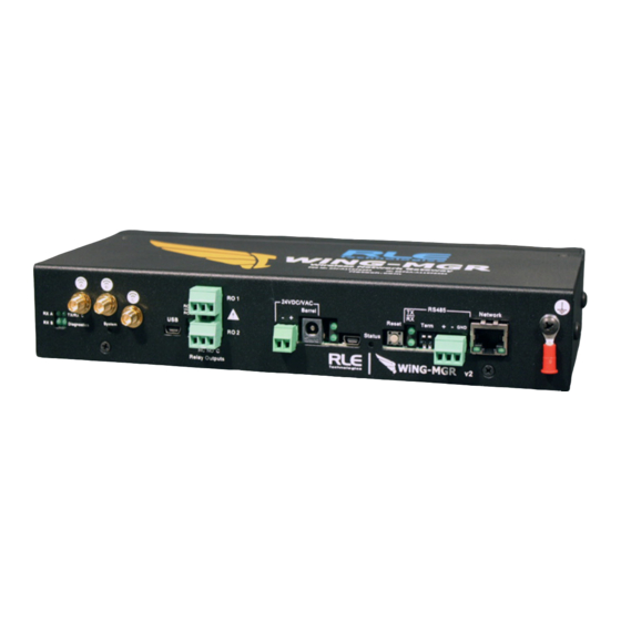
24 VDC/VAC Power terminal block Barrel Wall adapter connector USB mini B connector RS485 Port RS485 circuit connector (+ - GND) Network 10/100 BASE-T connector Ethernet port Earth ground connection Table 1.2 WiNG-MGR Physical Connection Descriptions WiNG-MGR v2 User Guide 800.518.1519... -
Page 13: Reset Button
Table 1.3 Reset Button Functions 1.5. SW1 Switch Settings SW1 functions as follows: Status Indicator Figure SW1-1 Not used SW1-2 EIA-485 Termination (On=100 ohm termination) Table 1.4 SW1 Switch Settings rletech.com WiNG-MGR v2 User Guide... - Page 14 System Overview WiNG-MGR v2 User Guide 800.518.1519...
-
Page 15: Getting Started
2.2.1 Power Supply and Ground Connections RLE Technologies recommends powering the WiNG-MGR from a UPS supply so the device can send alarm notifications during a power outage. The device can be powered through either the barrel or the power supply terminal block, but you must use only one of these power options at a time - you cannot connect to both power sources simultaneously or damage will occur. -
Page 16: Figure 2.1 Power Supply And Grounding Connections
If you’re providing your own power supply, connect 24VDC to the unit through the power terminal block. Power unit through EITHER the terminal block or barrel, but NOT BOTH! Grounding Figure 2.1 Power Supply and Grounding Connections WiNG-MGR v2 User Guide 800.815.1519... -
Page 17: Wired Relay Outputs
The Ethernet port supports Web browser access, email (SMTP), BACnet secondary, Modbus server, and SNMP. Use an Ethernet cable to connect the device directly to a PC or to a hub or switch. Figure 2.3 Ethernet Connection to a PC Using an Ethernet Cable rletech.com WiNG-MGR v2 User Guide... -
Page 18: Modbus Eia-485 Connections
The WiNG-MGR can function as a Modbus server over an EIA-485, 2-wire hardware connection, as shown in Figure 2.5. When using the EIA-485 port for Modbus RTU communication, RLE Technologies recommends an 18AWG shielded twisted pair stranded copper wire for the connection, using no more than 2000 feet (609.6m) of wire at this specification. -
Page 19: Antenna
WiNG-MGR is configured. Change the IP address and Subnet Mask of the computer from its existing address to one that will allow it to communicate with the WiNG-MGR, such as . It may be 10.0.0.189 rletech.com WiNG-MGR v2 User Guide... -
Page 20: Set The Ip Address Via Usb Connection
Default Gateway address your IT Department provided for the unit. Press the enter key. For example, DG 192.168.103.1 Type and press the enter key to reset the WiNG-MGR and apply the changes. REBOOT WiNG-MGR v2 User Guide 800.815.1519... -
Page 21: Deploy Your Sensors
Set Notification Parameters For Your Sensors WiNG sensors can be configured to trigger alarm and warning messages when their reading surpass set notification thresholds. Alarm and warning parameters can be set per individual sensor or across all sensors at once. rletech.com WiNG-MGR v2 User Guide... -
Page 22: Global Sensor Settings
This is listed as the ID # in the upper right corner of each sensor’s individual configuration page. If you’d like, place a label or other marking on the sensor case to show its index number. Figure 2.7 Sensor Serial Number and Index Number WiNG-MGR v2 User Guide 800.815.1519... -
Page 23: Web Interface
Figure 3.1 Dashboard Navigation Option Description Header Icons Detailed in “Header Icons” on page 25 Left Side Navigation Left Side Navigation items each have their own documented section within this chapter. Table 3.1 Dashboard Navigation Options rletech.com WiNG-MGR v2 User Guide... - Page 24 Serial Number filled in ascending order, from highest to lowest. Page numbers also appear in the lower right side of this section. Click the appropriate number to move among the pages. Table 3.1 Dashboard Navigation Options WiNG-MGR v2 User Guide 800.518.1519...
-
Page 25: Header Icons
Sensor Discovery Wizard Modal The wizard will locate all sensors within the range of the WiNG-MGR that are not already associated with this unit. They will all list in the modal window. Each sensor has a rletech.com WiNG-MGR v2 User Guide... -
Page 26: Figure 3.4 Sensor Discovery Wizard - Select The Sensors For This Wing-Mgr
Once you have configured all you alarm parameters, your sensor discovery is complete. Be sure to save a copy of the system configuration. Reference “Sensors” on page 58 to download the sensors CSV file for safekeeping. WiNG-MGR v2 User Guide 800.518.1519... -
Page 27: Refresh
If you need to contact RLE’s technical support team, you’ll be asked for the information found in the system information modal window. Figure 3.6 System Information 3.1.6 Sign In/Out Use this option to sign into and out of the WiNG-MGR user interface. rletech.com WiNG-MGR v2 User Guide... -
Page 28: Sensors
Battery The amount of battery life left in the 3.6V AA Lithium battery in this sensor. Status An icon that tells, at a glance, the status of the sensor. Table 3.2 Sensor Page Field Descriptions WiNG-MGR v2 User Guide 800.518.1519... -
Page 29: Individual Sensor
This page shows the wireless network metrics for this individual sensor. RSSI metrics for the manager and range extender system components can be found under the Wireless Network Metrics link in the left side navigation. These sensor metrics are provided for advanced users rletech.com WiNG-MGR v2 User Guide... -
Page 30: 3.2.1.3 Activity History
loss of sensor connection is expected Table 3.3 Wireless Network Metrics Field Descriptions 3.2.1.3 Activity History This page shows the activity history for this sensor. Figure 3.10 Individual Sensor Page - Activity History Tab WiNG-MGR v2 User Guide 800.518.1519... -
Page 31: 3.2.1.4 Sensor Configuration
Humidity Under Enter a low humidity alarm threshold - if the humidity drops below this value, a low humidity alarm is generated. Table 3.4 Individual Sensor Page - Sensor Configuration Tab Options rletech.com WiNG-MGR v2 User Guide... - Page 32 To fine tune the accuracy of the humidity reading, enter an offset value here. The offset value is a percent humidity amount in 1% increments. Use - for negative offsets. Table 3.4 Individual Sensor Page - Sensor Configuration Tab Options WiNG-MGR v2 User Guide 800.518.1519...
- Page 33 <Previous Sensor Configure the previous sensor in the list. Next Sensor> Configure the next sensor in the list. Table 3.4 Individual Sensor Page - Sensor Configuration Tab Options rletech.com WiNG-MGR v2 User Guide...
-
Page 34: 3.2.1.5 Sensor Objects
Web Interface 3.2.1.5 Sensor Objects This page denotes the individual Modbus, BACnet, and SNMP objects provided for this particular sensor. Figure 3.12 Individual Sensor Page - Sensor Objects Tab WiNG-MGR v2 User Guide 800.518.1519... -
Page 35: Wireless Network Metrics
-80 to -90 = Fair signal strength, occasional packet loss expected -90 and beyond = Poor signal strength, frequent packet loss and loss of sensor connection is expected Table 3.5 Wireless Network Metrics Field Descriptions rletech.com WiNG-MGR v2 User Guide... -
Page 36: Alarms
Each sensor’s name is a link. Click this link to visit the individual sensor’s status and configuration page. Here you can view the sensor’s logged data, as well as edit and configure the sensor’s settings and alarm and warning thresholds. Figure 3.14 Alarms Page WiNG-MGR v2 User Guide 800.518.1519... -
Page 37: Map
Sensor Map text to pop the map out into a new browser tab. Complete instructions for creating this map are found in section 3.6.5, “Mapping” on page 44. Figure 3.15 Map Page rletech.com WiNG-MGR v2 User Guide... -
Page 38: System Configuration
Designate a technical contact for this unit. System Location Specify the physical location of this particular WiNG-MGR. Asset Tag If your facility uses asset tagging, log the code for this WiNG-MGR. Table 3.6 Identity Configuration Options WiNG-MGR v2 User Guide 800.518.1519... -
Page 39: Ip Page
The WiNG-MGR is shipped with a default Subnet Mask of 255.255.255.0. Contact your IT Department for an appropriate Subnet Mask, if you wish to change this field. Default subnet mask: 255.255.255.0 Table 3.7 IP Configuration Options rletech.com WiNG-MGR v2 User Guide... - Page 40 If you choose not to use DHCP, Enter a static IPv6 address in this field. Static Router Enter static router information here. Prefix Length If the static address has a prefix, enter the bit length of the prefix here. Table 3.7 IP Configuration Options WiNG-MGR v2 User Guide 800.518.1519...
-
Page 41: Time
Wi-MGR will synchronize. Commonly used public NTP servers include us.pool.ntp.org and time.nist.gov Default setting: blank Time Zone Select the time zone in which this particular WiNG-MGR resides. Default setting: Western European (UTC + 0) Table 3.8 Time Configuration Options rletech.com WiNG-MGR v2 User Guide... - Page 42 NTP server you designated and synchronize its time with the NTP server. If you enter a 0 in this field it disables this feature, which also disables NTP. Default setting: 0 (disabled) Table 3.8 Time Configuration Options WiNG-MGR v2 User Guide 800.518.1519...
-
Page 43: Relay Outputs
Read the relay status with the 0x01 (Read Coil) command • Reset LATCHED relays only with the 0x05 (Write single coil) or the 0x15 (Write multiple coils) command Default: Alarm Table 3.9 Relay Output Configuration Options rletech.com WiNG-MGR v2 User Guide... -
Page 44: Mapping
Edit Graphically: Click the icon to adjust the sensor’s location directly on the map.This is the easiest way to edit the map. • Remove: Click the “x” to remove the sensor from the map. Table 3.10 Mapping Configuration Options WiNG-MGR v2 User Guide 800.518.1519... -
Page 45: Figure 3.21 Mapped Point Confirmation Message
The map will launch in a new tab. The point you have chosen to edit is detailed in the fields at the top of the map and is also represented in a blue box with a red highlight on the map. You are mapping this sensor rletech.com WiNG-MGR v2 User Guide... - Page 46 Once all of your points are positioned and sized correctly, click the Save button on the top right side of the screen. Click the Exit button to return to the Mapping page of the web interface. WiNG-MGR v2 User Guide 800.518.1519...
-
Page 47: Communications
Set the unit/station ID to 0 disable EIA-485 port communications. Default: 0 (disabled) Baud Rate The baud rate is selectable: 9600, 19200, or 38400. Choose the appropriate baud rate. Default: 9600 Table 3.11 EIA-485 Configuration Options rletech.com WiNG-MGR v2 User Guide... -
Page 48: Modbus
The default unit identifier is 0, which disables this feature. To enable this option, enter a TCP address from 1-254 in this field. In most instances, the identifier is typically set at 1. Default: 0 (disabled) Table 3.12 Modbus Configuration Options WiNG-MGR v2 User Guide 800.518.1519... -
Page 49: Bacnet
BACnet station ID the WiNG manager will attempt to discover. This should match the highest station ID in the MS/TP ring. All devices in the ring should have the same Max Master value configured. Table 3.13 BACnet Configuration Options rletech.com WiNG-MGR v2 User Guide... -
Page 50: Dns
Enter the IP address for the primary DNS server, as provided by your internet service provider. Default setting: 0.0.0.0 Secondary DNS Enter the IP address for the secondary DNS server, as provided by your internet service provider. Default setting: 0.0.0.0 Table 3.14 DNS Configuration Options WiNG-MGR v2 User Guide 800.518.1519... -
Page 51: Smtp
Refer to this field to see how many email messages are pending and how many have been sent by the WiNG-MGR. This is a quick way to check if email notifications are being sent by the WiNG-MGR. Table 3.15 SMTP Configuration Options rletech.com WiNG-MGR v2 User Guide... -
Page 52: E-Mail
If you would like a message to be sent to a distribution group, you can use the email address of the distribution group in one of these fields. Table 3.16 Email Configuration Options WiNG-MGR v2 User Guide 800.518.1519... -
Page 53: Snmp
When communicating via SNMP V1/V2, identify devices that receive Traps and/or Syslog messages from the WiNG-MGR and communicate with the WiNG-MGR over the network. Get / Read Enter the appropriate community name. Set / Write Enter the appropriate community name. Table 3.17 SNMP Configuration Options rletech.com WiNG-MGR v2 User Guide... - Page 54 Enter the authentication password - the password must be between (8-24 chars) 8 and 24 characters long. Priv. Password (8-24 Enter the privacy (encryption) password - the password must be chars) between 8 and 24 characters long. Table 3.17 SNMP Configuration Options WiNG-MGR v2 User Guide 800.518.1519...
-
Page 55: Admin
Figure 3.29 XML Page Option Description XML Options Download Sensor Click this link to download sensor information as an .xml file. XML File Table 3.18 XML Configuration Options rletech.com WiNG-MGR v2 User Guide... -
Page 56: Firmware
WiNG-MGR v1 into a WiNG-MGR v2. As an alternative, you can download the sensor CSV file from a WiNG-MGR v1 and upload it to a WiNG-MGR v2 via the Admin > Sensors page. Not all the configuration settings will transfer, but the sensor names and their locations will upload. - Page 57 Update Firmware The WiNG-MGR requires multiple firmware files. When new firmware is available for the WiNG-MGR radio, download the file from the website and upload the WiNG-MGR radio file here. Table 3.19 Firmware Configuration Options rletech.com WiNG-MGR v2 User Guide...
-
Page 58: Sensors
If you do not turn off the sensor discovery feature, the WiNG-MGR will continue to try to find new sensors. This can contaminate your list of active sensors with additional sensors that do not actually exist. Table 3.20 Sensor Configuration Options WiNG-MGR v2 User Guide 800.518.1519... - Page 59 WiNG-MGR systems simultaneously. Note: You can upload a CSV file downloaded from a WiNG-MGR v1 into a WiNG-MGR v2. Not all of the configuration settings will transfer, but the sensor names and locations will upload. Download Sensor...
-
Page 60: Radios
- the manager, sensors, and range extenders - are all operating on the correct channel pairs. Figure 3.32 Radios Page Attribute Description Settings Radios A & B Radios A and B communicate with the WiNG sensors. (Anaren) Default: On Table 3.21 Radio Configuration Options WiNG-MGR v2 User Guide 800.518.1519... - Page 61 WiNG-MGR’s radios. The Spectrum field tells you if this unit operates on the 900MHz or 868MHz frequency. If you need to make a call to RLE tech support, they may request information found in these fields. Table 3.21 Radio Configuration Options rletech.com WiNG-MGR v2 User Guide...
-
Page 62: Alarms
If you do not check the checkbox next to the alarm parameter, that value will not be applied to the sensors in your system. Table 3.22 Alarms Configuration Options WiNG-MGR v2 User Guide 800.518.1519... - Page 63 Enter a high humidity warning threshold - if the humidity rises above this value, a high humidity warning is generated. Check the box to activate the option, and enter a humidity value. Table 3.22 Alarms Configuration Options rletech.com WiNG-MGR v2 User Guide...
- Page 64 The number of seconds that pass between the time a temperature or humidity reading goes into a warning state and the time that warning is announced. Check the box to activate the option and enter a time interval. Table 3.22 Alarms Configuration Options WiNG-MGR v2 User Guide 800.518.1519...
-
Page 65: Users
View Only - This user can view pages within the web interface but cannot make any changes to settings or configuration. • Administrator - This user can view data and make changes to settings and configuration options. Table 3.23 Users Configuration Options rletech.com WiNG-MGR v2 User Guide... -
Page 66: Radius
Enter the RADIUS secret. The secret is used between the RADIUS client and the RADIUS server to encrypt passwords. The secret is administered by the server and must be known to the client. Table 3.24 Radius Configuration Options WiNG-MGR v2 User Guide 800.518.1519... - Page 67 Radius Username Enter a username to test Radius Password Enter a password to test Last Server Test Results - The results from the server and the authorization level will be displayed. Table 3.24 Radius Configuration Options rletech.com WiNG-MGR v2 User Guide...
-
Page 68: Certificate
Use this field to upload the HTTPS certificate. Upload Key Use this field to upload the HTTPS key. Delete Certificate Click this button to delete the uploaded certificate and key from the and Key Data WiNG-MGR. Table 3.25 Certificate Configuration Options WiNG-MGR v2 User Guide 800.518.1519... -
Page 69: Modbus Communications
The function field is one byte in length and tells the WiNG-MGR which function to perform. The supported functions are 03 (Read 4xxxx output registers), 04 (Read 3xxxx input registers), 06 (Preset single register), 16 (Preset multiple registers). rletech.com WiNG-MGR v2 User Guide... -
Page 70: 4.1.1.3 Data Field
Byte count (1 byte) # of registers to read (2 bytes) First register (2 bytes) Crc Checksum (2 bytes) Second register (2 bytes) … Crc Checksum (2 bytes) Table 4.2 Read Output Registers Packet Structure WiNG-MGR v2 User Guide 800.518.1519... -
Page 71: Function 06: Preset Single Register & Function 16
3, “Relay Outputs” on page 43. The master must then send a Preset Single or Preset Multiple Register request packet. Register Name Description Units Range 49001 Relay K1 Relay 1 Activation: 1=active, 0=inactive uint16 49002 Relay K2 Relay 2 Activation: 1=active, 0=inactive uint16 Table 4.4 Preset Single and Multiple Registers rletech.com WiNG-MGR v2 User Guide... -
Page 72: Rtu Framing
Response Sample Unit ID 2 responds to Function Code 4 with six bytes of hexadecimal data and ends with CRC16 checksum. Register Values: 40001 = 0000 (hex) 40002 = 0000 (hex) 40003 = 0001 (hex) WiNG-MGR v2 User Guide 800.518.1519... -
Page 73: Wing-Rxt
(Class II circuits). The power to the WiNG-RXT must be supplied from a limited energy circuit: 5VDC with a maximum available current of 10A or a Class 2 circuit. rletech.com WiNG-MGR v2 User Guide... - Page 74 WiNG-RXT WiNG-MGR v2 User Guide 800.518.1519...
-
Page 75: Communications Objects
Register, Instance, and OID assignments and a direct connection between the sensor number and the communications objects. A formula at the end of the table will help you calculate BACnet Instances and SNMP OIDs. rletech.com WiNG-MGR v2 User Guide... -
Page 76: Table A.1 Modbus Registers, Bacnet Instances, And Snmp Oids
= ai: 2803 – av: n01 = av: 2801 – av: n02 = av: 2802 SNMP Object Identifiers are as follows, where the last digit, n, is replaced with the sensor’s sensor number WiNG-MGR v2 User Guide 800.518.1519... - Page 77 – 1.3.6.1.4.1.3184.1.15.2.2.1.2.n 1.3.6.1.4.1.3184.1.15.2.2.1.2.28 – 1.3.6.1.4.1.3184.1.15.2.2.1.3.n 1.3.6.1.4.1.3184.1.15.2.2.1.3.28 – 1.3.6.1.4.1.3184.1.15.2.2.1.4.n 1.3.6.1.4.1.3184.1.15.2.2.1.4.28 – 1.3.6.1.4.1.3184.1.15.2.2.1.6.n 1.3.6.1.4.1.3184.1.15.2.2.1.6.28 – 1.3.6.1.4.1.3184.1.15.2.2.1.7.n 1.3.6.1.4.1.3184.1.15.2.2.1.7.28 – 1.3.6.1.4.1.3184.1.15.2.2.1.8.n 1.3.6.1.4.1.3184.1.15.2.2.1.8.28 – 1.3.6.1.4.1.3184.1.15.2.2.1.9.n 1.3.6.1.4.1.3184.1.15.2.2.1.9.28 – 1.3.6.1.4.1.3184.1.15.2.2.1.10.n 1.3.6.1.4.1.3184.1.15.2.2.1.10.28 – 1.3.6.1.4.1.3184.1.15.2.2.1.11.n 1.3.6.1.4.1.3184.1.15.2.2.1.11.28 – 1.3.6.1.4.1.3184.1.15.2.2.1.12.n 1.3.6.1.4.1.3184.1.15.2.2.1.12.28 rletech.com WiNG-MGR v2 User Guide...
- Page 78 WiNG-MGR v2 User Guide 800.518.1519...
-
Page 79: Update Firmware
- may become corrupted during the firmware update. If the configuration files do become corrupted, the downloaded configuration files serves as a backup, and can be uploaded to the system to restore the lost data. Use the MIME feature to upload the configuration file. rletech.com WiNG-MGR v2 User Guide... -
Page 80: Load The Application Firmware
Verify that your PC and the WiNG-MGR are on the same subnet (LAN). Open your TFTP client. Configure the client as follows. Host = WiNG-MGR’s IP Address Port = 69 Block Size = 64, 128, 256, 512, or 1024 WiNG-MGR v2 User Guide 800.518.1519... - Page 81 Do the same with the second firmware file. After one minute, refresh the WiNG-MGR’s web page. Notice that the Flash field now contains the latest firmware. Click the “Start Application” button to reboot the unit. rletech.com WiNG-MGR v2 User Guide...
- Page 82 WiNG-MGR v2 User Guide 800.518.1519...
-
Page 83: C Alternate Channel Pair Communications
If you look inside this hole you will see a small black button. You will use this button to change the channel pair of this sensor. Sensor Channel Pair Button Figure C.1 Sensor Channel Pair Button rletech.com WiNG-MGR v2 User Guide... -
Page 84: Manager Communications
1, and click the Save Changes button. Then verify the WiNG-MGR is communicating on channel pair 1 by checking the System LED and ensuring it blinks blue. WiNG-MGR v2 User Guide 800.518.1519... -
Page 85: Add A Range Extender To A Wing System
2 picking up an entirely different set of sensors. This too is fine. Just remember the sensors you’re trying to pick up must be on the same channel pair at the device that should be receiving their signal. rletech.com WiNG-MGR v2 User Guide... - Page 86 Alternate Channel Pair Communications WiNG-MGR v2 User Guide 800.518.1519...
-
Page 87: Troubleshooting
Below you’ll find troubleshooting tips for a variety of situations you may encounter with the WiNG-MGR. Please use these suggestions to troubleshoot your appliance. If these troubleshooting tips do not resolve your issues, RLE Technologies offers personalized support for all our products. If you require customer support for your WiNG-MGR, please contact RLE Technologies directly: Email: support@rletech.com... - Page 88 Bring the sensor closer to the WiNG-MGR. Run the sensor discovery wizard again. If the sensor does not show in the wizard when it is close to the WiNG-MGR, contact your local sales representative or RLE Technologies. If the sensor does show in the wizard, move the sensor back to its original location.
-
Page 89: Sensor Troubleshooting
Troubleshooting D.2. Sensor Troubleshooting The WiNG-MGR is designed to work with a RLE Technologies’ WiNG sensors. Sometimes, problems may occur with the sensors that affect the way they interact with the WiNG-MGR. Use the following guidelines to troubleshoot WiNG sensors. - Page 90 Troubleshooting WiNG-MGR v2 User Guide 800.518.1519...
-
Page 91: E Technical Specifications
MGR; 400 sensors per WiNG-MGR may be accomplished with range extenders, but signal conflict will increase. Antenna Three (3) 868-928MHz with RP/SMA connectors Login Security Web browser access (Ethernet); Four (4) users and passwords can be configured Table E.1 WiNG-MGR Technical Specifications rletech.com WiNG-MGR v2 User Guide... - Page 92 Up to 600 ft (183m) direct line of sight to WiNG sensors. Up to 270 ft (82.3m) through one wall to WiNG sensors. Up to 100 ft (30.5m) through multiple walls to WiNG sensors. Indicators Table E.2 WiNG-RXT Technical Specifications WiNG-MGR v2 User Guide 800.518.1519...
- Page 93 ETL listed; CE; conforms to UL 61010-1, EN 61010; EN 61326-1; EN 301489-1; certified to CSA C22.2 NO, 61010.1; RoHS compliant; FCC ID X7J-A11072401 and MCQ-XB900HP; IC 8975A-A11072401 and 1846A- XB900HP Table E.2 WiNG-RXT Technical Specifications (continued) rletech.com WiNG-MGR v2 User Guide...
- Page 94 Technical Specifications WiNG-MGR v2 User Guide 800.518.1519...
Need help?
Do you have a question about the WiNG-MGR v2 and is the answer not in the manual?
Questions and answers