Table of Contents
Advertisement
Quick Links
Advertisement
Table of Contents
Troubleshooting

Related Manuals for RLE Technologies WiNG-MGR


Summary of Contents for RLE Technologies WiNG-MGR
- Page 1 WiNG System WiNG-MGR WiNG-RXT User Guide Version 1.3 Firmware Version 3.3.2...
-
Page 2: Revision History
Raymond & Lae Engineering, Inc. are subject to the limited warranty, limited liability, and other terms and conditions of sale set forth at rletech.com. Revision History Rev. No. Date June 2017 June 2017 October 2017 WiNG-MGR User Guide 800.518.1519... -
Page 3: Product Registration
Product Serial Number Product Manufacture Date The WiNG-MGR is not a field-serviceable item and must be sent back to RLE Technologies for mechanical repair. Only RLE certified service personnel is allowed to access the interior of this equipment, and power must be disconnected (unplugged) from the WiNG-MGR any time the unit is mechanically serviced. - Page 4 Purchaser has ordered a product conforming to Purchaser's specifications, or conforming to Purchaser's specific design. Purchaser has not relied and shall not rely on any oral representation regarding the Product sold hereunder and any oral representation shall not bind Seller and shall not be part of any warranty. WiNG-MGR User Guide 800.518.1519...
-
Page 5: Table Of Contents
IP ............... . . 40 rletech.com WiNG-MGR User Guide... - Page 6 Packet Communications for the WiNG-MGR........
-
Page 7: Rletech.com Wing-Mgr User Guide
WiNG-MGR Physical Connections ........ - Page 8 Modbus Communications ..........69 WiNG-RXT .
- Page 9 Table 1.2 WiNG-MGR Physical Connection Descriptions ....... 12 Table 1.3 SW1 Switch Settings .
- Page 10 WiNG-MGR Technical Specifications........
-
Page 11: System Overview
YSTEM VERVIEW HAPTER 1.1. Product Description The WiNG-MGR is a wireless sensor network manager that receives signals from wireless devices and relays them to facilities monitoring systems as SNMP, Modbus TCP/IP, Modbus RTU, BACnet/IP, and BACnet MS/TP signals. 1.2. Indicators The LEDs on the WiNG-MGR indicate the status of a variety of actions. -
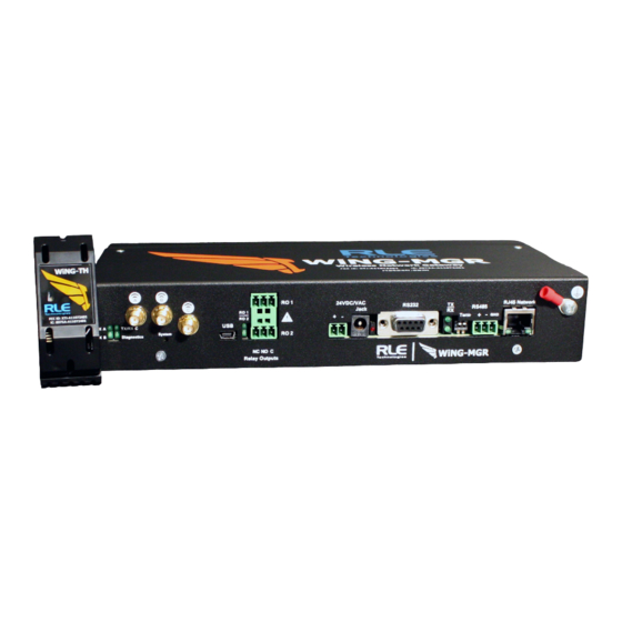
Page 12: Physical Connections
Label Description System Indicates on which radio communications channel set the manager is operating: • Blue blink pattern - WiNG-MGR is operating on the primary 900MHz 900MHz channel set. WiNG-MGR • Green blink pattern - WiNG-MGR is operating on the alternate 900MHz channel set. -
Page 13: Sw1 Switch Settings
System Overview 1.4. SW1 Switch Settings Status Indicator Figure SW1-1 Not used SW1-2 EIA-485 Termination (On=100 ohm termination) Table 1.3 SW1 Switch Settings rletech.com WiNG-MGR User Guide... - Page 14 System Overview WiNG-MGR User Guide 800.518.1519...
-
Page 15: Getting Started
Wall mount tabs are sold separately. ♦ Mount the WiNG-MGR in either the front or the back of a 19-inch rack - You will need two of RLE’s L-shaped rack mount tabs (included with the WiNG-MGR). Remove the screws from the sides of the WiNG-MGR, put the tabs in place, and reapply the screws. -
Page 16: Wiring
2.2.1 Power Supply and Ground Connections RLE Technologies recommends powering the WiNG-MGR from a UPS supply so the device can send alarm notifications during a power outage. The device can be powered through either the jack or the power supply terminal block, but you must use only one of these power options at a time - you cannot connect the power jack and terminal block power simultaneously or damage will occur. -
Page 17: Wired Relay Outputs
2.2.2 Wired Relay Outputs The WiNG-MGR accommodates two wired relay outputs. Any relay output connections must be made with double insulated wire (jacketed multi-conductor cable). If you wish to use this functionality, wire the connections now. Your wiring may look similar to the connections shown here: Figure 2.2... -
Page 18: Connectivity
2.3.1 RJ45 Ethernet Connection The WiNG-MGR has an internal 10/100BASE-T Ethernet port that is used for configuration. The Ethernet port supports Web browser access, email (SMTP), BACnet slave, Modbus slave, and SNMP. The device can connect directly to a PC with a crossover cable, or it can connect to a PC through a hub or switch, with CAT5 cables. -
Page 19: Com Connection
2.3.2 EIA-232 COM Connection The WiNG-MGR can be connected directly to a PC through its EIA-232 port. This is useful for IP configuration, firmware downloads, and troubleshooting. The EIA-232 connection is only used as a temporary connection. Connect the straight through, 9-pin serial cable as shown in Figure 2.5. -
Page 20: Antenna
B can be close together, but to avoid signal interference they both need to be as far away from antenna C as possible. Extend the leader cables on the antennas to their fullest lengths and secure the antennas as far away from the WiNG-MGR - and as high off the ground - as possible. -
Page 21: Communication: Set The Ip Address
. This default address must be changed to an IP address that 255.255.255.0 corresponds with the user’s network before the WiNG-MGR can communicate over the network. There are two ways to set the WiNG-MGR’s IP address: via the web browser or via the EIA-232 interface. 2.4.1 Set the IP Address Using a Web Browser Attention: If you have not set an IP address before, consult your IT Department for support. -
Page 22: Set The Ip Address Via Eia-232 Connection
IT Department provided for the unit. Press the enter key. For example, The WiNG-MGR will reboot after the Default Gateway is changed. DG 192.168.103.1 The IP address is now set and the WiNG-MGR can be accessed through a Web browser using the new IP address. WiNG-MGR User Guide... -
Page 23: Deploy Your Sensors
The sensor discovery wizard is the recommended method to use when associating sensors with a WiNG-MGR. It has a variety of benefits, including the ability to pick and choose which specific sensors are added to a particular WiNG-MGR installation. Since sensor discovery... -
Page 24: Individual Sensor Configuration
♦ Although each sensor has a unique serial number, the WiNG-MGR will also assign each sensor an index number. This is listed as the ID # in the upper right corner of each sensor’s individual configuration page. If you’d like, place a label or other marking on the sensor case to show its index number. -
Page 25: Web Interface
Web interface, you must first configure the WiNG-MGR to communicate via the Internet. To set the IP address, see section 2.4., “Communication: Set the IP Address” on page 21. Use the Dashboard to access and view the data collected and managed by the WiNG-MGR. Header Icons Left Side Navigation Figure 3.1... - Page 26 These blocks reflect the current status of the sensors connected to the WiNG-MGR. Section B This is your view of the sensors associated with this WiNG-MGR. A drop down lets you choose how many sensors display per page. Select 10, 25, 50, or 100, depending on your preference.
-
Page 27: Header Icons
Relay Output Status Click on this link to access a modal window that provides a quick way to view the status of the WiNG-MGR’s relay outputs. Click the X in the upper right corner of the box to close the modal window. -
Page 28: Figure 3.4 Sensor Discovery Wizard - Select The Sensors For This Wing-Mgr
Web Interface checkbox in front of it. If you would like the sensor to be associated with this WiNG-MGR, leave the checkbox checked. Uncheck the boxes next to the sensors that should NOT be configured within this WiNG-MGR at this time. Verify the serial numbers of the sensors to ensure you’re adding the correct sensors. -
Page 29: Refresh
Instead of waiting for the WiNG-MGR to refresh on its own, click the link to force a system refresh. -
Page 30: Sensors
3.2. Sensors The Sensors page allows users to view all the sensors accessible through the WiNG-MGR and also serves at the unit’s dashboard view. The drop down menu allows you to decide how many sensors will be displayed per page. -
Page 31: Individual Sensor
Metrics link in the left side navigation. These sensor metrics are provided for advanced users with a strong knowledge of RF. You may also need to provide them to your technician if you engage in a technical support call. rletech.com WiNG-MGR User Guide... -
Page 32: 3.2.1.3 Activity History
High LQI values - above 25 or 30 - indicate a noisy environment. Table 3.3 Wireless Network Metrics Field Descriptions 3.2.1.3 Activity History This page shows the activity history for this sensor. Figure 3.10 Individual Sensor Page - Activity History Tab WiNG-MGR User Guide 800.518.1519... -
Page 33: 3.2.1.4 Sensor Configuration
You must access the Admin > Sensors configuration page and select the “Run Hours” option from the Battery Meter Type dropdown if you wish to use this functionality. Table 3.4 Individual Sensor Page - Sensor Configuration Tab Options rletech.com WiNG-MGR User Guide... - Page 34 Gain/Offset Settings - Applicable only for WiNG-ANLG analog sensors. Using the formulas below, adjust the gain and offset values approproately to fine tune your sensor’s accuracy. Table 3.4 Individual Sensor Page - Sensor Configuration Tab Options WiNG-MGR User Guide 800.518.1519...
- Page 35 <Previous Sensor Configure the previous sensor in the list. Next Sensor> Configure the next sensor in the list. Table 3.4 Individual Sensor Page - Sensor Configuration Tab Options rletech.com WiNG-MGR User Guide...
-
Page 36: 3.2.1.5 Sensor Objects
Web Interface 3.2.1.5 Sensor Objects This page denotes the individual Modbus, BACnet, and SNMP objects provided for this particular sensor. Figure 3.12 Individual Sensor Page - Sensor Objects Tab WiNG-MGR User Guide 800.518.1519... -
Page 37: Wireless Network Metrics
If you are working to maximize this WiNG system, the RSSI value will likely plateau close to -30. The closer you can get your reading to -30, the better performance you’ll see. Table 3.5 Wireless Network Metrics Field Descriptions rletech.com WiNG-MGR User Guide... -
Page 38: Alarms
Alarms The Alarms page shows all active alarms and warnings reported by sensors monitored by this WiNG-MGR. If the sensors has returned to normal since the alarm or warning was reported, this will be noted in the table as well. -
Page 39: System Configuration
3.5.1 Identity The Identity page allows you to customize the name of the WiNG-MGR and the contact and location information for this particular WiNG-MGR. You can also look here to find the unit’s serial number, model number, MAC address, and the version of firmware currently running on the unit. -
Page 40: Table 3.7 Ip Configuration Options
Web Interface 3.5.2 The WiNG-MGR can communicate via IPv4, IPv6, or both IPv4 and IPv6. Select the option that is most appropriate for your network, and configure the fields as necessary. Figure 3.16 IP Page Option Description IP Settings Network Statistics Click this link to view advanced network statistics for this device. - Page 41 Edit this field in accordance with your ISPs security settings. Default: 0 = Port 80 IPv6 Settings- Configure these fields if the WiNG-MGR is communicating via IPv6. You do have the option in this section to use DHCP. If you do choose to enable DHCP, DHCP will override any static options you configure.
-
Page 42: Time
3.5.3 Time The WiNG-MGR has an onboard clock that timestamps alarms and other logged events. If you’d like, you can set the onboard clock manually. If you configure the Network Time Protocol (NTP) settings, the NTP server will automatically adjust the time of the onboard clock and keep it in synch with the time reported by the NTP server. - Page 43 Default setting: First Sunday - November Update Interval This interval tells the WiNG-MGR how often it should access the NTP server you designated and synchronize its time with the NTP server. If you enter a 0 in this field it disables this feature, which also disables NTP.
-
Page 44: Relay Outputs
Web Interface 3.5.4 Relay Outputs The WiNG-MGR has two hard-wired relay outputs labeled K1 and K2. Use this tab to individually configure the relay outputs. Use the individual sensor pages to designate when a sensor alarm activates a relay output. -
Page 45: Communications
Communications The communications options allow you to configure how the WiNG-MGR conveys its information to individuals and other devices. 3.6.1 EIA-485 If the WiNG-MGR will communicate via the EIA-485 port, configure the necessary options here. Figure 3.19 EIA-485 Configuration Option... - Page 46 - this help avoid executing a reboot while someone is performing maintenance on or configuring a unit. Reset MSTP Port - The WiNG-MGR will reset the MSTP port once it detects no activity on the port for two minutes.
-
Page 47: Modbus
The default slave unit identifier is 0, which disables this feature. To enable this option, enter a TCP/UDP slave address from 1-254 in this field. In most instances, the identifier is typically set at 1. Default: 0 (disabled) Table 3.11 Modbus Configuration Options rletech.com WiNG-MGR User Guide... -
Page 48: Bacnet
Web Interface 3.6.3 BACnet If the WiNG-MGR will communicate via the BACnet, configure the necessary options here. Figure 3.21 BACnet Configuration Option Description Pics Click this link to view the Bacnet identifiers and objects supported by the WiNG-MGR. Packet Log Click this link to view the Bacnet packet log. -
Page 49: Table 3.12 Bacnet Configuration Options
Time, in seconds, for foreign device discovery. MS/TP Max Master The Max Master is the highest master address that a device will attempt to discover. Designate this device’s Max Master here. Table 3.12 BACnet Configuration Options rletech.com WiNG-MGR User Guide... -
Page 50: Dns
Enter the IP address for the primary DNS server, as provided by your internet service provider. Default setting: 0.0.0.0 Secondary DNS Enter the IP address for the secondary DNS server, as provided by your internet service provider. Default setting: 0.0.0.0 Table 3.13 DNS Configuration Options WiNG-MGR User Guide 800.518.1519... -
Page 51: Smtp
Email Stats Refer to this field to see how many email messages are pending and how many have been sent by the WiNG-MGR. This is a quick way to check if email notifications are being sent by the WiNG-MGR. Table 3.14 SMTP Configuration Options rletech.com... -
Page 52: E-Mail
Mail Subject Enter the text that will appear in the subject line of any outgoing email messages. Mail Sender Address Any email messages sent by the WiNG-MGR will come from this valid email address. Table 3.15 Email Configuration Options WiNG-MGR User Guide 800.518.1519... -
Page 53: Snmp
Enter the address of the WiNG-MGR’s physical location. V1/V2C Community Names When communicating via SNMP V1/V2, identify devices that receive Traps and/or Syslog messages from the WiNG-MGR and communicate with the WiNG-MGR over the network. Get / Read Enter the appropriate community name. - Page 54 Designate whether traps will be sent via IPv4 or IPv6. Max. Inform Retries If the communication of a trap fails, this is the maximum number of times the WiNG-MGR will re-send the trap. Inform Interval This is the amount of time that lapses between re-sends.
-
Page 55: Admin
3.7.1 XML/Logging The WiNG-MGR collects quite a bit of data. Right click the Download File button on this page and select Save Link As or Save Target As to download this data as an XML file. You can then take that file and import it into a spreadsheet for viewing, logging, and analyzing. -
Page 56: Firmware
Web Interface 3.7.2 Firmware RLE releases firmware upgrades that add new features and functionality to the WiNG-MGR. Firmware updates are free of charge. Download firmware updates from the RLE website and load them onto your system here. Figure 3.27 Firmware Page... - Page 57 Web Interface Attribute Description Reset to Factory If you should need to restore your WiNG-MGR to its factory default Defaults settings, click this button. NOTE - Clicking the Reset Factory Default button will overwrite all system and sensor settings you have established within the WiNG-MGR, and will erase all logged data within the unit.
-
Page 58: Sensors
There are some global configuration options that are applicable to all sensors in the system. Those options are configurable on the Sensors page. The Sensors page also holds the link for the Sensor Auto Discovery, which is used to add new sensors to the WiNG-MGR’s sensor network. - Page 59 Wi-MGR. Delete Sensors Delete Sensor If you wish to delete some sensors monitored by the WiNG-MGR Range without deleting all the sensors, use this option. Enter the range of sensors you wish to delete, and click the Delete button. If you wish to delete one specific sensor, enter that sensor’s number as both the...
-
Page 60: Radios
If you wish to change the channel pair on which your system is Channel Pair communicating, refer to Appendix C, “Alternate Channel Pair Communications” on page 91. Default: Channel pair 1 Table 3.20 Radio Configuration Options WiNG-MGR User Guide 800.518.1519... - Page 61 Radio Status - These fields provide detailed information about the status and operation of the WiNG-MGR’s radios. The Spectrum field tells you if this unit operates on the900MHz or 868MHz frequency. If you need to make a call to RLE tech support, they may request information found in these fields.
-
Page 62: Alarms
There are a set of global configuration settings that can be applied to all sensors associated with this WiNG-MGR. Any global settings configured on this page will apply to all the sensors associated with this WiNG-MGR. If you already have parameters set up for your sensors, they will be overwritten when you apply these global alarm settings. - Page 63 Offline Delays Users can designate how many minutes must pass before the WiNG-MGR considers the sensor offline. Check the box to activate the option, and enter a time interval. Global Warning Settings - There is a checkbox next to each individual alarm setting.
- Page 64 The number of seconds that pass between the time the system goes into a warning state and the time that warning is announced. Check the box to activate the option, and enter a time interval. Table 3.21 Alarms Configuration Options WiNG-MGR User Guide 800.518.1519...
-
Page 65: Users
3.7.6 Users The WiNG-MGR allows you to configure user privileges for up to eight unique users. User 1 is always the Administrator’s slot. Use users 2 - 8 to either configure users with read only access, or to configure additional Admin accounts. -
Page 66: Radius/Ldap
Web Interface 3.7.7 Radius/LDAP If you would like to configure Radius/LDAP settings for your WiNG-MGR, do so here. Figure 3.32 Radius/LDAP Page Option Description Radius/LDAP Settings Authentication Use the drop down menu to select either RADIUS or LDAP authentication. IP Version Designate the IP version for communications. - Page 67 Username/LDAP Enter a username to test Filter Radius Password Enter a password to test Last Server Test Results - The results from the server and the authorization level will be displayed. Table 3.23 Radius/LDAP Configuration Options rletech.com WiNG-MGR User Guide...
- Page 68 Web Interface WiNG-MGR User Guide 800.518.1519...
-
Page 69: Modbus Communications
Com Port1/Modbus/Bacnet Configuration web page. 4.1.1.2 Function Field The function field is one byte in length and tells the WiNG-MGR which function to perform. The supported functions are 03 (Read 4xxxx output registers), 04 (Read 3xxxx input registers), 06 (Preset single register), 16 (Preset multiple registers). -
Page 70: 4.1.1.3 Data Field
4.1.2 Exception Responses If a Modbus master sends an invalid command to the WiNG-MGR or attempts to read an invalid register, an exception response is generated. The response packet will have the high order bit of the function code set to one. The data field of the exception response contains the exception error code. -
Page 71: Function 04: Read Input Registers
Read Output Registers 4.2.2 Function 04: Read Input Registers To read the WiNG-MGR’s input values, the master must send a Read Input Registers request packet. The Read Input Registers request packet specifies a start register and the number of registers to read. -
Page 72: Function 06: Preset Single Register & Function 16: Preset Multiple Registers
0=inactive 49002 Relay K2 Relay 2 Activation: 1=active, uint16 0=inactive Table 4.6 Preset Single and Multiple Registers 4.3. RTU Framing The example below shows a typical Query/Response from a WiNG-MGR. Register Register Register Slave Function Count Bytes Data Data Data... -
Page 73: Wing-Rxt
WiNG-MGR - and has high off the ground - as possible. Access the WiNG-MGR’s web interface and navigate to the Admin > Radio Configuration page. Radio C needs to be on in order for the WiNG-MGR to communicate with the WiNG-RXT. - Page 74 WiNG-RXT WiNG-MGR User Guide 800.518.1519...
-
Page 75: Communications Objects
BJECTS HAPTER The WiNG-MGR can communicate via Modbus, BACnet, and SNMP. Each sensor has its own Modbus Registers, BACnet Instances, and SNMP Object Identifiers (OIDs). This table is provided for reference. Please note that the values presented in Reading #2 and Reading #3 will vary depending on the type of sensor with which you are working. -
Page 76: Table A.1 Modbus Registers, Bacnet Instances, And Snmp Oids
40016 av: 201 1.3.6.1.4.1.3184.1.15.2.2.1.9.2 Percentage (uint16) Out of Service 40017 1.3.6.1.4.1.3184.1.15.2.2.1.10.2 (uint16) Age of Sensor 40018 av: 202 1.3.6.1.4.1.3184.1.15.2.2.1.11.2 Data (seconds) (uint32) Offline Delay 40020 1.3.6.1.4.1.3184.1.15.2.2.1.12.2 (uint16) Table A.1 Modbus Registers, BACnet Instances, and SNMP OIDs WiNG-MGR User Guide 800.518.1519... - Page 77 40036 av: 401 1.3.6.1.4.1.3184.1.15.2.2.1.9.4 Percentage (uint16) Out of Service 40037 1.3.6.1.4.1.3184.1.15.2.2.1.10.4 (uint16) Age of Sensor 40038 av: 402 1.3.6.1.4.1.3184.1.15.2.2.1.11.4 Data (seconds) (uint32) Offline Delay 40040 1.3.6.1.4.1.3184.1.15.2.2.1.12.4 (uint16) Table A.1 Modbus Registers, BACnet Instances, and SNMP OIDs rletech.com WiNG-MGR User Guide...
- Page 78 40056 av: 601 1.3.6.1.4.1.3184.1.15.2.2.1.9.6 Percentage (uint16) Out of Service 40057 1.3.6.1.4.1.3184.1.15.2.2.1.10.6 (uint16) Age of Sensor 40058 av: 602 1.3.6.1.4.1.3184.1.15.2.2.1.11.6 Data (seconds) (uint32) Offline Delay 40060 1.3.6.1.4.1.3184.1.15.2.2.1.12.6 (uint16) Table A.1 Modbus Registers, BACnet Instances, and SNMP OIDs WiNG-MGR User Guide 800.518.1519...
- Page 79 40076 av: 801 1.3.6.1.4.1.3184.1.15.2.2.1.9.8 Percentage (uint16) Out of Service 40077 1.3.6.1.4.1.3184.1.15.2.2.1.10.8 (uint16) Age of Sensor 40078 av: 802 1.3.6.1.4.1.3184.1.15.2.2.1.11.8 Data (seconds) (uint32) Offline Delay 40080 1.3.6.1.4.1.3184.1.15.2.2.1.12.8 (uint16) Table A.1 Modbus Registers, BACnet Instances, and SNMP OIDs rletech.com WiNG-MGR User Guide...
- Page 80 40096 av: 1001 1.3.6.1.4.1.3184.1.15.2.2.1.9.10 Percentage (uint16) Out of Service 40097 1.3.6.1.4.1.3184.1.15.2.2.1.10.10 (uint16) Age of Sensor 40098 av: 1002 1.3.6.1.4.1.3184.1.15.2.2.1.11.10 Data (seconds) (uint32) Offline Delay 40100 1.3.6.1.4.1.3184.1.15.2.2.1.12.10 (uint16) Table A.1 Modbus Registers, BACnet Instances, and SNMP OIDs WiNG-MGR User Guide 800.518.1519...
- Page 81 40116 av: 1201 1.3.6.1.4.1.3184.1.15.2.2.1.9.12 Percentage (uint16) Out of Service 40117 1.3.6.1.4.1.3184.1.15.2.2.1.10.12 (uint16) Age of Sensor 40118 av: 1202 1.3.6.1.4.1.3184.1.15.2.2.1.11.12 Data (seconds) (uint32) Offline Delay 40120 1.3.6.1.4.1.3184.1.15.2.2.1.12.12 (uint16) Table A.1 Modbus Registers, BACnet Instances, and SNMP OIDs rletech.com WiNG-MGR User Guide...
- Page 82 40136 av: 1401 1.3.6.1.4.1.3184.1.15.2.2.1.9.14 Percentage (uint16) Out of Service 40137 1.3.6.1.4.1.3184.1.15.2.2.1.10.14 (uint16) Age of Sensor 40138 av: 1402 1.3.6.1.4.1.3184.1.15.2.2.1.11.14 Data (seconds) (uint32) Offline Delay 40140 1.3.6.1.4.1.3184.1.15.2.2.1.12.14 (uint16) Table A.1 Modbus Registers, BACnet Instances, and SNMP OIDs WiNG-MGR User Guide 800.518.1519...
- Page 83 40156 av: 1601 1.3.6.1.4.1.3184.1.15.2.2.1.9.16 Percentage (uint16) Out of Service 40157 1.3.6.1.4.1.3184.1.15.2.2.1.10.16 (uint16) Age of Sensor 40158 av: 1602 1.3.6.1.4.1.3184.1.15.2.2.1.11.16 Data (seconds) (uint32) Offline Delay 40160 1.3.6.1.4.1.3184.1.15.2.2.1.12.16 (uint16) Table A.1 Modbus Registers, BACnet Instances, and SNMP OIDs rletech.com WiNG-MGR User Guide...
- Page 84 40176 av: 1801 1.3.6.1.4.1.3184.1.15.2.2.1.9.18 Percentage (uint16) Out of Service 40177 1.3.6.1.4.1.3184.1.15.2.2.1.10.18 (uint16) Age of Sensor 40178 av: 1802 1.3.6.1.4.1.3184.1.15.2.2.1.11.18 Data (seconds) (uint32) Offline Delay 40180 1.3.6.1.4.1.3184.1.15.2.2.1.12.18 (uint16) Table A.1 Modbus Registers, BACnet Instances, and SNMP OIDs WiNG-MGR User Guide 800.518.1519...
- Page 85 40196 av: 2001 1.3.6.1.4.1.3184.1.15.2.2.1.9.20 Percentage (uint16) Out of Service 40197 1.3.6.1.4.1.3184.1.15.2.2.1.10.20 (uint16) Age of Sensor 40198 av: 2002 1.3.6.1.4.1.3184.1.15.2.2.1.11.20 Data (seconds) (uint32) Offline Delay 40200 1.3.6.1.4.1.3184.1.15.2.2.1.12.20 (uint16) Table A.1 Modbus Registers, BACnet Instances, and SNMP OIDs rletech.com WiNG-MGR User Guide...
- Page 86 SNMP Object Identifiers are as follows, where the last digit, n, is replaced with the sensor’s sensor number – 1.3.6.1.4.1.3184.1.15.2.2.1.2.n 1.3.6.1.4.1.3184.1.15.2.2.1.2.28 – 1.3.6.1.4.1.3184.1.15.2.2.1.3.n 1.3.6.1.4.1.3184.1.15.2.2.1.3.28 – 1.3.6.1.4.1.3184.1.15.2.2.1.4.n 1.3.6.1.4.1.3184.1.15.2.2.1.4.28 – 1.3.6.1.4.1.3184.1.15.2.2.1.6.n 1.3.6.1.4.1.3184.1.15.2.2.1.6.28 – 1.3.6.1.4.1.3184.1.15.2.2.1.7.n 1.3.6.1.4.1.3184.1.15.2.2.1.7.28 – 1.3.6.1.4.1.3184.1.15.2.2.1.8.n 1.3.6.1.4.1.3184.1.15.2.2.1.8.28 – 1.3.6.1.4.1.3184.1.15.2.2.1.9.n 1.3.6.1.4.1.3184.1.15.2.2.1.9.28 – 1.3.6.1.4.1.3184.1.15.2.2.1.10.n 1.3.6.1.4.1.3184.1.15.2.2.1.10.28 – 1.3.6.1.4.1.3184.1.15.2.2.1.11.n 1.3.6.1.4.1.3184.1.15.2.2.1.11.28 – 1.3.6.1.4.1.3184.1.15.2.2.1.12.n 1.3.6.1.4.1.3184.1.15.2.2.1.12.28 WiNG-MGR User Guide 800.518.1519...
-
Page 87: Update Firmware
Before updating any firmware, go to the web interface and access the Admin menu, and then the Firmware tab. Download the WiNG-MGR’s system configuration file and save it in a safe location. -
Page 88: Load The Application Firmware
B.1. Load the Application Firmware Once the WiNG-MGR’s configuration file and the latest version of firmware files have been downloaded to a local drive, navigate to the Firmware tab within the Admin menu in the web interface. Figure B.2 Admin Menu, Firmware Page - Firmware File Upload Navigate to the first file using the browse button, and then click on upload for the unit to take the file. -
Page 89: Load The Firmware Using Tftp
Note The file must be sent in BINARY (not ASCII). Send or PUT the first firmware file to the WiNG-MGR. It may take ~10 seconds for the firmware upload to begin. Do the same with the second firmware file. After one minute, refresh the WiNG-MGR’s web page. Notice that the Flash field now contains the latest firmware. - Page 90 WiNG-MGR User Guide 800.518.1519...
-
Page 91: C Alternate Channel Pair Communications
If you look inside this hole you will see a small black button. You will use this button to change the channel pair of this sensor. Sensor Channel Pair Button Figure C.1 Sensor Channel Pair Button rletech.com WiNG-MGR User Guide... -
Page 92: Manager Communications
Manager Channel Frequency Pair 2. Click the Save Changes button to execute the channel pair change. Once the changes have been saved, look at the LED on the front of the WiNG-MGR. It blinks green to indicate it is operating on channel pair 2. -
Page 93: Add A Range Extender To A Wing System
WiNG-MGR - and has high off the ground - as possible. Access the WiNG-MGR’s web interface and navigate to the Admin > Radio Configuration page. Radio C needs to be on in order for the WiNG-MGR to communicate with the WiNG- RXT. - Page 94 Alternate Channel Pair Communications WiNG-MGR User Guide 800.518.1519...
-
Page 95: Troubleshooting
Contact RLE Technologies for further troubleshooting. You cannot view the WiNG-MGR’s home page. Verify that the WiNG-MGR is powered up and running. You will see lights on the RJ45 (Ethernet) port illuminated and flashing. If no lights are illuminated on the unit, the unit may not be powered. - Page 96 If the sensor is not visible on the WiNG-MGR’s home page, look at the top of the sensor and see if the LED is blinking. If you do not see a blink, check the sensor’s batteries. If you do see it blink, continue to step 2.
-
Page 97: Sensor Troubleshooting
Sensor Troubleshooting The WiNG-MGR is designed to work with a RLE Technologies’ WiNG sensors. Sometimes, problems may occur with the sensors that affect the way they interact with the WiNG-MGR. Use the following guidelines to troubleshoot WiNG sensors. The sensor does not seem to be working. It may have a battery problem. - Page 98 Troubleshooting WiNG-MGR User Guide 800.518.1519...
-
Page 99: E Technical Specifications
868-870MHz / 902-928MHz Max Number of Wireless Sensors RLE recommends not exceeding 250 sensors per WiNG- Per Manager MGR; 400 sensors per WiNG-MGR may be accomplished with range extenders, but signal conflict will increase. Antenna Three (3) 868-928MHz with RP/SMA connectors... -
Page 100: Table E.2 Wing-Rxt Technical Specifications
ETL listed; CE; conforms to UL 61010-1, EN 61010; certified to CSA C22.2 NO, 61010.1; RoHS compliant; FCC ID X7J-A11072401 and MCQ-XB900HP; IC 8975A- A11072401 and 1846A-XB900HP Table E.1 WiNG-MGR Technical Specifications (continued) WiNG-RXT Power 5VDC @ 400mA max. USB Communications Port... -
Page 101: Table E.3 Wing Sensor Technical Specifications
+/- 0.2°C from 10°C to 60°C +/- 0.5°C from -40°C to 85°C Maximal +/- 0.4°C from 10°C to 60°C +/- 1.0°C from -40°C to 85°C Temperature and Humidity Sensor Accuracy Table E.3 WiNG Sensor Technical Specifications rletech.com WiNG-MGR User Guide... - Page 102 Free standing, magnets (included), 1U screw, 15mm mini din rail, zip ties Dimensions 2.8"L x 1.1”W x 1.1"H (7.1cmL x 2.8cmW x 2.8cmH) Weight 0.08lb (0.036kg) Certifications CE; FCC ID XJ7-A11072401; IC 8975A-A11072401 Table E.3 WiNG Sensor Technical Specifications (continued) WiNG-MGR User Guide 800.518.1519...
Need help?
Do you have a question about the WiNG-MGR and is the answer not in the manual?
Questions and answers