Table of Contents
Advertisement
Quick Links
Advertisement
Table of Contents

Related Manuals for RLE Technologies Falcon FMS


Summary of Contents for RLE Technologies Falcon FMS
- Page 1 Facilities Monitoring System User Guide Version 1.6 Firmware Version 8.6.16...
- Page 2 Copyright and Trademark Notices © Raymond & Lae Engineering, Inc. 2011. All rights reserved. RLE® is a registered trademark and Seahawk™, Falcon™, and Raptor™ are trademarks of Raymond & Lae Engineering, Inc. The products sold by Raymond & Lae Engineering, Inc. are subject to the limited warranty, limited liability, and other terms and conditions of sale set forth at http://rletech.com/RLE-Terms-and-Conditions.html.
- Page 3 Access and submit Product Registration information from the FMS Configuration Menu. Any information provided to RLE Technologies through the registration form will be regarded as confidential. RLE will not sell or distribute any of the information to third parties. To read our Privacy Policy, please visit our website: www.rletech.com.
- Page 4 RLE Product Warranty Seller warrants to the Ultimate Purchaser (the purchaser who buys for use and not for resale) that all products furnished under this order and which are manufactured by Seller will conform to final specifications, drawings, samples and other written descriptions approved in writing by Seller, and will be free from defects in materials and workmanship.
-
Page 5: Table Of Contents
Falcon FMS Wiring ........ - Page 6 Trap Log ..............46 Relays .
- Page 7 Configuring Inputs and Relays for Slave Units (Modbus, SNMP, or BACnet) ....97 Modbus/SNMP Slave Units Configuration—Modbus Generic (Typical) ..... . . 100 Unit Number Links .
- Page 8 Wiring for Other Falcon FMS Accessories........
- Page 9 Figures System Overview ........... 15 Figure 1.1 FMS 2U Front Panel Indicators and Controls .
- Page 10 FMS Configuration ..........49 Figure 4.1 Initial Login for the FMS .
- Page 11 Figure 5.7 Modbus Packet Log ..........95 Figure 5.8 Modbus Rest Port Confirmation .
- Page 12 Figure 9.1 FMS Dial-Up Menu ..........140 Point-to-Point Protocol .
- Page 13 Tables System Overview ..........15 Table 1.1 Terminal Block Designations.
- Page 14 Table E.1 Analog Alarm ID Reference Table – Inputs 1 through 8 ....171 Table E.2 Analog Alarm Reference Table – Input Slots 1 and 2 ....172 Table E.3 Analog Alarm Reference Table –...
-
Page 15: System Overview
H A P T E R YSTEM VERVIEW HAPTER 1.1. Product Description The Falcon Facilities Monitoring System (FMS) is a comprehensive system which provides additional equipment protection by monitoring critical operating parameters in enterprises, remote network facilities, communication rooms, remote and unmanned facilities, and critical support systems. -
Page 16: Front Panel Indicators And Controls
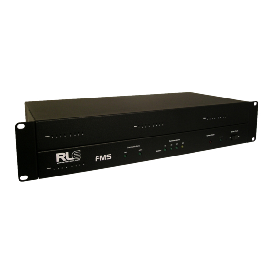
System Overview 1.2. Front Panel Indicators and Controls Figure 1.1 FMS 2U Front Panel Indicators and Controls Expansion Card Relay Status LEDs ♦ Green (On) if the relay is active-for Expansion Card A only. Network LEDs – Two Network Status LEDs ♦... -
Page 17: Terminal Block Designations
System Overview 1.3. Terminal Block Designations Figure 1.2 FMS Terminal Block Designations Table 1.1 Terminal Block Designations TB1-1 (+) Input for 24 or 48VDC (optional) power TB1-2 (-) Input for 24 or 48VDC (optional) power 24VDC wall adapter input (center +) (not available with 48VDC version) TB2-1 24VDC positive (+) external output (power for sensors) TB2-2... - Page 18 System Overview Table 1.1 Terminal Block Designations (continued) TB3-10 24VDC ground external output (power for sensors) TB4-1 Relay 1 normally closed (NC) TB4-2 Relay 1 normally open (NO) TB4-3 Relay 1 common (C) TB4-4 Relay 2 normally closed (NC) TB4-5 Relay 2 normally open (NO) TB4-6 Relay 2 common (C)
-
Page 19: Rear Panel Indicators
System Overview 1.4. Rear Panel Indicators The rear panel of the FMS houses a series of green LEDs. The chart below tracks indicator status when the corresponding green LED is illuminated: Status Indicator K1 (Output Relay) Relay is energized. EIA-232 TX (COM2) Data is being transmitted. - Page 20 System Overview FMS User Guide 800.518.1519...
-
Page 21: Getting Started
2.1. Installation The Falcon FMS comes in a 19 inch (.48m) rack mount enclosure. Install the FMS in the rack. Use the proper anchoring method to mount the unit securely. Supply either 24VDC (standard) or 48VDC (optional) to the unit. -
Page 22: Universal Input Connections
Getting Started Figure 2.1 24VDC Power Supply Connection For a 48VDC model FMS, connect a 48VDC supply through a circuit breaker to TB1 as shown below. In telecommunications applications, the 48VDC supply is typically connected to the 48VDC battery system through a DC distribution panel. Figure 2.2 48VDC Power Supply Connection 2.2.2 Universal Input Connections The eight non-isolated universal inputs are connected to TB2 and TB3. -
Page 23: Figure 2.3 Universal Input Wiring Examples
Getting Started Note The Falcon has 24VDC available (TB2-1, TB2-2 +24VDC, TB3-9, TB3-10 24VDC comm.) to power external sensors. The 24VDC external supply is internally fused at 300mA. Figure 2.3 Universal Input Wiring Examples Some equipment may have several dry contact outputs with a Common Ground. Connect this equipment as shown in Figure 2.4. -
Page 24: Relay 1 And 2 Connections
Getting Started 2.2.3 Relay 1 and 2 Connections Relay outputs may be used to unlatch doors, signal annunciators, signal IP cameras, and to turn on auxiliary equipment such as exhaust fans. Relay outputs are form c (spdt). Refer to specifications in Appendix D, “FMS Accessories Wiring”... -
Page 25: Keypad Connection
Getting Started 2.2.4 Keypad Connection The FMS can be configured with a 3 x 4 keypad interface. Entering a user code, configured through software, activates a relay output which unlatches a door and allows an individual to enter the secure area. Entering the correct user code can also trigger a relay output to signal an IP camera to snap a picture and email it to a predefined recipient. -
Page 26: Rj11 Phone Line Connection
Getting Started 2.2.6 RJ11 Phone Line Connection The FMS may contain an optional internal modem for dial in and dial out capabilities. The modem can be used for: ♦ Email notification through an Internet Service Provider (ISP). ♦ Remote connection to accomplish a variety of tasks, including: viewing alarms, changing IP Configurations, and acknowledging alarms. -
Page 27: Modbus Eia-485 Connections
Getting Started 2.2.8 Modbus EIA-485 Connections The FMS can function as a Modbus Master or Slave over an EIA-485, 2-wire hardware connection. Figure 2.10 FMS EIA-485 Connection rletech.com FMS User Guide... -
Page 28: Modbus Eia-232 Connections
Getting Started 2.2.9 Modbus EIA-232 Connections The FMS can function as a Modbus Master or Slave over an EIA-232 hardware connection. The EIA-232 port is configured as a DTE device. Figure 2.11 FMS EIA-232 Connection to a DCE or DTE Device FMS User Guide 800.518.1519... -
Page 29: Expansion Card A Connections
Getting Started 2.2.10 Expansion Card A Connections A sticker identifying the expansion cards as A or C is located on each Expansion Card. The following wiring diagrams show the Expansion Card in slot 1. However, the Expansion Card may be in Slot 2, 3 or 4 based on the FMS configuration. The I/O for each card type appears on the back of the FMS for reference during field wiring;... -
Page 30: Figure 2.14 Dry Contact Inputs With Ground And Relay Outputs, Expansion Card A
Getting Started Figure 2.14 Dry Contact Inputs with Ground and Relay Outputs, Expansion Card A FMS User Guide 800.518.1519... -
Page 31: Expansion Card C Connections
Getting Started 2.2.11 Expansion Card C Connections Expansion Card C has 24 dry contact input channels. Figure 2.15 I/O Terminals for Expansion Card C Figure 2.16 Typical Wiring for Expansion Card C rletech.com FMS User Guide... -
Page 32: Communication
Getting Started 2.3. Communication The FMS will not communicate over a user’s network the first time it is connected to the network. The manufacturer programs the FMS with a default IP address: 10.0.0.188, Subnet Mask: 255.255.255.0. This default address must be changed to an IP address that corresponds with the user’s network before the FMS can communicate over the network. -
Page 33: Use The Ping Command
Getting Started 2.3.2.3 Use the PING Command After the ARP command has been entered, the PING command must be entered from the same computer in order to set up the IP address of the FMS. The PING command will use the ARP entry added from 2.3.2.1, “Obtain the Ethernet Address (MAC Address)”... -
Page 34: Set The Fms Ip Address Using An Eia-232 Connection
Default Gateway address. To change the Default Gateway address, type DG, <space> and the new address to be assigned, then press the enter key, example: DG 192.168.1.1 <enter>. Every time you make a change the Falcon FMS will automatically save the changes. Chapter 8, “EIA-232 Interface” on page 135, for more information on the EIA-232 command set. -
Page 35: Fms Web Interface
H A P T E R FMS W NTERFACE HAPTER The FMS Web interface provides a convenient way to check and monitor the FMS status via the Web. To access the FMS Main Menu, or Home page, type the IP address of the FMS into the location bar of the Web browser. -
Page 36: Identity
FMS Web Interface The bottom of the FMS Main Menu features columns that list the FMS configured inputs. The number of inputs displayed is configurable from the Configuration menu; see Chapter 4, “FMS Configuration” on page 49. Each input has a box with its number, name, and status. The box is shaded to signal the inputs status. -
Page 37: Configuration
FMS Web Interface 3.3. Configuration The Configuration link provides access to a series of menus from which qualified users can make adjustments to the FMS settings; see Chapter 4, “FMS Configuration” on page 49, for more details. Figure 3.3 Configuration Page rletech.com FMS User Guide... -
Page 38: History
FMS Web Interface 3.4. History The History link provides access to a wide variety of logged historical data for the FMS. 3.4.1 Alarm History Alarm History displays the last 256 alarms captured by the FMS. Alarms are ranked from most recent (top of the list) to least recent (bottom of the list). Figure 3.4 Alarm History Page The following format is used to record each alarm entry: AH###-ID-Condition-Date Time (Value UOM) Label... -
Page 39: Event History
FMS Web Interface Alarms by Code button. Acknowledge codes are set under the Phone Number or Email Configuration pages; see Chapter 4, “FMS Configuration” on page 49, for more information on configuring phone numbers. 3.4.2 Event History Event History displays the past 100 events, as recorded by the FMS. Typical events that are logged include System Booted, Email Accepted by Server, No Dial Tone, Busy, No Carrier, Page Successful, Alarm History Cleared, Digital Status History Cleared, Force Acknowledge by <initials>, Program Upload - TFTP. -
Page 40: Keypad Access History
FMS Web Interface 3.4.4 Keypad Access History Keypad Access History displays the last 100 keypad entries captured by the FMS. Figure 3.7 Keypad Access History View The following information is displayed: ♦ Access Log Index (ALxxx) ♦ Date and Time of Event ♦... -
Page 41: Data
FMS Web Interface 3.4.6 Data Data History provides an intermediate page to assist in navigating to the desired data. Only points configured as analog 4-20mA are shown. Figure 3.9 Data History Page ♦ The Modbus Points links at the bottom of the page are shown if the FMS is equipped with the EXP-MBCS option. -
Page 42: Data History Text Downloads
FMS Web Interface per day for the last seven days. These values can be downloaded to a comma separated value (.csv) file via the Data History Text Downloads button. This link is located on the right side of every Text data history page Figure 3.10 Minute Page 3.4.6.2 Data History Text Downloads... -
Page 43: Alarm History Text (Alarmhistory.txt)
3.4.6.4 Graph This graph allows users to see a Java-based line graph of any analog point on the Falcon FMS. Using the mouse, stretch or compress the X-axis to adjust the resolution of the time display. Stretch or compress the Y-axis to adjust the resolution of the analog value. Hover over the legend to display the graphed values. -
Page 44: Figure 3.14 Java Loading Image
FMS Web Interface The first time you display a graph, you might see the following Java image as Java loads on your system: Figure 3.14 Java Loading Image FMS User Guide 800.518.1519... -
Page 45: Trends
3.4.7 Trends Users can view a Java-based graph or download a .CSV file by clicking on the links on this page. The Falcon FMS can track extending trending for up to 32 physical and/or Modbus points. Figure 3.15 Extended Trends Page rletech.com... -
Page 46: Trap Log
FMS Web Interface 3.4.8 Trap Log This page allows users to view trap information sent from the Falcon FMS to a Network Management Software (NMS). Figure 3.16 Example Trap Log 3.5. Relays Relays displays the current status of each FMS relay output. The Status field is color coded. -
Page 47: Url Links
FMS Web Interface 3.6. URL Links URL Links displays still images (.jpg) from all IP cameras and other URLs linked to the FMS. Figure 3.18 Example Still Images from IP Cameras 3.7. Refresh Click this link to refresh the FMS web interface. rletech.com FMS User Guide... - Page 48 FMS Web Interface FMS User Guide 800.518.1519...
-
Page 49: Fms Configuration
H A P T E R FMS C ONFIGURATION HAPTER 4.1. FMS Web Interface Overview The FMS Web interface provides a convenient way to configure basic settings from any Internet-enabled computer. This chapter will walk users through the steps of configuring the FMS. -
Page 50: Figure 4.1 Initial Login For The Fms
FMS Configuration ♦ Network Statistics ♦ ICMP Ping ♦ Email/DNS ♦ Network Time Protocol ♦ SNMP/Syslog ♦ BACnet ♦ Com Port1/Modbus/SNMP/Telnet ♦ Modbus/SNMP Slave Units ♦ PUE/DCiE/Summary ♦ ♦ Flash Program ♦ Product Registration The FMS is shipped to the user with the IP address configured as and a Subnet 10.0.0.188 Mask of... -
Page 51: Homepage And Configuration Menu
FMS Configuration These pre-configurations can be customized through the System link on the Configuration Menu of the Web interface. To change the FMS IP address, refer to 2.3.1, “Set the FMS IP Address” on page The “Smart Browsing” feature available with some browsers complicates use of the FMS Web interface. -
Page 52: Inputs And Relays
FMS Configuration 4.3. Inputs and Relays Input and Relay allows users to program specific parameters for each FMS input and relay. Different FMS models allow different numbers of inputs and relays. Only installed inputs and relays are displayed. Inputs and relays are identified by their name and slot channel number (S.Ch). -
Page 53: Main Board Input Configuration (Channels 1-8)
FMS Configuration 4.3.1 Main Board Input Configuration (Channels 1-8) To configure the FMS main board inputs (channels 1-8), select the appropriate input number. A page similar to Figure 4.5 will appear. Figure 4.5 FMS Main Board Input Configuration The number of the input that is being configured appears in the upper bar. Options on this configuration page are described below. -
Page 54: Figure 4.6 Gain And Offset Calculator
FMS Configuration Select Input Type: Select based on the type of device connected to the input channel. Options include: ♦ Not Configured: Select when there is nothing connected to the input. ♦ Analog 4-20mA: Select when the device connected to the input provides a 4-20mA output. ♦... - Page 55 FMS Configuration Enter the sensor’s range and press the Calculate button. Click the Return to Input 1 Configuration link so that the gain and offset fields are automatically entered with the correct offset and gain settings. Gain and offset values can also be determined by using the following formulas: Gain for 4-20mA Transducer = (Sensor High Range Value- Sensor Low Range Value) / 4 Offset for 4-20mA Transducer = Sensor Low Range Value - Gain...
- Page 56 FMS Configuration 1 and High Limit 2 are disabled when they are both set to 0. High Limit 2 will also activate any designated relays. High Limit 1: Applies only when the input type is set for Analog 4-20mA. The FMS will record an alarm and send notification when the FMS calculated value exceeds this limit.
-
Page 57: Figure 4.7 Noi/Nc Wiring Example
(only one common input connection) and only the NO or NC contacts are available for each individual relay output. See the example below or see 2.2., “Falcon FMS Wiring” on page 21, for more information. Example: Configure input channels 1-2 for Individual Ground, and configure input channels 4-6 for Common Ground. - Page 58 FMS Configuration BACnet Instance: The BACnet object identifier. It is a numerical code used to identify the input. This code must be unique within the BACnet device. BACnet Units: A numerical code used to assign engineering units to this BACnet Instance. Refer to the BACnet standard for further information.
-
Page 59: Expansion Card "A" Input Configuration
FMS Configuration 4.3.2 Expansion Card “A” Input Configuration To configure Expansion Card A, select the desired input or relay from the Input and Relay Configuration page; see Figure 4.4, “FMS Input/Output Configuration Menu” on page While units will vary depending on individual configurations, Expansion Card A is typically numbered 1.1-1.12, 2.1-2.12, etc. -
Page 60: Expansion Card "C" Input Configuration
FMS Configuration 4.3.3 Expansion Card “C” Input Configuration To configure Expansion Card C, select the desired input or relay from the Input and Relay Configuration page; see Figure 4.4, “FMS Input/Output Configuration Menu” on page While units will vary depending on individual configurations, Expansion Card C is typically numbered 1.1-1.24, 2.1-2.24, etc. -
Page 61: Relay Configuration
FMS Configuration 4.3.4 Relay Configuration A screen similar to Figure 4.10 will be displayed when configuring relays. The following options are available on this page: Figure 4.10 Relay Configuration Page Type: Each relay output can be configured for one of the following types-only one type per relay output: ♦... -
Page 62: Figure 4.11 Keypad/Relay Configuration
FMS Configuration Figure 4.11 Keypad/Relay Configuration ♦ Button Controlled: Adds a button to the Relay Control page allowing users with Read- Only privileges to turn on or off a relay output for control purposes. ♦ Modbus Controlled: Configures the relay output to be controlled by a Modbus/SNMP Slave device in alarm. -
Page 63: System
FMS Configuration Relay Control Logic will either OR or AND the OR'd Alarm and AND'd Alarm inputs together. The Relay Control Logic diagram in Appendix G, “Relay Control Logic” on page 185, shows how the OR'd Alarm IDs, AND’d Alarm IDs and the Combo Gate are internally connected. -
Page 64: Figure 4.13 Pda Width Configuration
FMS Configuration System Name: Appears on the FMS Main Menu. The system name is also included as part of email and pager notifications. Web Title Bar Text: Appears at the top of every FMS webpage. This text will be visible when the FMS webpage is minimized. -
Page 65: Alarm Management
FMS Configuration HTML Main Page Points: Determines the number of monitoring points displayed on the Main Menu. With the default of “0,” the Summary Alarm Box, Internal Temperature and Humidity Box and a link to View All Points are displayed. Settings greater than “0” will display the selected points with links to the remaining points. -
Page 66: Trends
FMS Configuration 4.6. Trends The Trends menu allows users to configure custom trending on an analog point, either physical or Modbus. Figure 4.15 Trends Configuration Page Data can be trended for up to 32 points. The FMS compiles 3840 entries per point. Once 3840 entries have been logged, the FMS eliminates 40 entries at a time and overwrites the data, from oldest to newest. -
Page 67: Clock
FMS Configuration 4.7. Clock The Clock page allows users to set the date and time on the FMS internal clock. Figure 4.17 Clock Configuration ♦ Enter the date using a MM/DD/YY format, where MM is a two digit month, DD is a two digit day, and YY is a two digit year. -
Page 68: Battery/Supply Voltage
FMS Configuration 4.9. Battery/Supply Voltage The Battery page allows users to configure power monitoring when the FMS is running off a 48V battery. Figure 4.19 Battery Page Battery/Supply Voltage Alarm: If the Installed option is selected, email notification can be sent to any previously designated recipient when the battery enters an alarm state. -
Page 69: Url Links (6-10)
FMS Configuration For Axis207 Web Cameras set the URL link to the following: ♦ URL Link #x Image: http://xxx.xxx.xxx.xxx/jpg/image.jpg ♦ URL Link #x Home: http://xxx.xxx.xxx.xxx ♦ URL Link #x Label: Enter the Camera’s Label For Panasonic KX-HCM110A Web Cameras, set the URL link to the following: ♦... -
Page 70: Nest/Egg
FMS Configuration 4.13. Nest/Egg The FMS contains a webpage, or “Nest,” that can monitor up to 32 other FMSs, or “Eggs.” The Nest will display the name and a summary alarm from each Falcon Egg. The summary alarm status of each Egg will automatically refresh based on the Web refresh rate determined for that individual FMS. -
Page 71: Egg Configuration
FMS Configuration Egg Login: Determine whether or not a login is requred to view the map. Nest Refresh Rate: How often the Nest view refreshes. Egg Refresh Rate: How often the Egg view refreshes. Nest/Map Coordinate: The spot on the map where the Nest is located. Designate the point by clicking the Graphical Mapping link and designating the locaton. -
Page 72: Modem/Phone Numbers
FMS Configuration 4.14. Modem/Phone Numbers/Pagers This link allows users to configure the FMS internal modem. This instructs the FMS when, how, and whom to call when an alarm occurs. Figure 4.26 Modem Configuration Initialization String: A maximum of 38 characters. &c1 and &d3 are mandatory. s0=1 sets the modem to answer after one ring. -
Page 73: Configure Phone Numbers
FMS Configuration Redial Attempts: Determines the number of times (1–255) to call a number until the call is successful. Enter 0 to disable this function. Redial Interval: Establishes the number of minutes (1–-255) to wait between redials. Enter 0 to disable this function. Force Alarm Acknowledge Code: Establishes a code that acknowledges all unacknowledged alarms. - Page 74 FMS Configuration ♦ Alphanumeric pager: The ID entered is sent to the paging service along with all queued alarm messages. The ID is the unique PIN for a specific pager. The ID may be a maximum of 16 characters. ♦ Numeric pager: The ID entered may be configured to deliver different numeric messages.
-
Page 75: Configure Phone Number 16 (Ppp)
FMS Configuration 4.14.2 Configure Phone Number 16 (PPP) This page is accessed through the 16 (PPP) link at the bottom of the Modem Configuration page. This screen allows users to configure a dial-up networking account. Figure 4.28 Phone Number 16 (PPP) Configuration DUN Phone #: Specifies the phone number of the Internet Service Provider (ISP) to connect DUN User Name: Enter your Internet Service Provider (ISP) account user name. -
Page 76: Internet Protocol
FMS Configuration Each ID Code/User can be selected as a Permanent or Temporary. Temporary users are only allowed access during the time specified in the Temporary Time drop box. This time may be set by selecting the Set Temporary Time button. Once the time frame has expired, the temporary users will not be allowed access. -
Page 77: User Administration (Web Access)
FMS Configuration TCP Max Seg Size: This adjusts the size of the web page packets being broadcast. Default size is set to 1436, you may need to set it to 536 for VPN access or satellite uplink networks. PPP Server: Sets the IP Address of the FMS network connection when accessing the FMS via its internal modem.This is required to allow a remote PC to view the FMS web pages over a dial-up connection;... -
Page 78: Network Statistics
FMS Configuration 4.18. Network Statistics Network Statistics: Displays network and EIA-485 statistics including: network packets received, packets transmitted, and errors. Figure 4.32 Network Statistics Page 4.19. ICMP Ping ICMP Ping: Allows a user to ping an IP address from the FMS. The results of the ping will display below in the “Last Ping Results”... -
Page 79: Email/Dns
FMS Configuration 4.20. Email/DNS Use the Email/DNS page to configure the FMS to send email notifications when inputs are in an alarm state. The FMS sends one email message per alarm instance to a maximum of eight email recipients. Figure 4.34 Email/DNS Configuration Page Access Type: Specifies whether to send the message through a local network or over a PPP dial-up connection. -
Page 80: Network Time Protocol
FMS Configuration Mail Recipient (1)–Mail Recipient (8): Specifies the addresses of up to eight email recipients. SMTP User Name: Used for ESMTP. Use the recommended default setting unless instructed differently by your IT Department. SMTP Password: Used for ESMTP. Use the recommended default setting unless instructed differently by your IT Department. -
Page 81: Snmp/Syslog
FMS Configuration 4.22. SNMP/Syslog SNMP/Syslog Configuration allows users to configure SNMP and Syslog notification options. Figure 4.36 SNMP Configuration Page System Name: Appears on the FMS Main Menu and is included as part of email and pager notifications. The System Name can also be viewed and changed in the System Configuration Menu. -
Page 82: Bacnet
FMS Configuration Choosing “falconPortTraps” requires more configuration at the NMS, but may make it easier to display, set severity, and parse the data in the NMS. Selecting “AlarmEntryAdded” enables the “AlarmEntryAdded” and “AlarmEntryRemoved” Trap. An “AlarmEntryAdded” Trap will be sent anytime a new alarm is added to the Alarm History log. -
Page 83: Com Port1/Modbus/Snmp/Telnet
FMS Configuration 4.24. Com Port1/Modbus/SNMP/Telnet These pages allow users to configure Com Port 1, Modbus, SNMP, and Telnet features. Configuration for Modbus/ Com Port 1 Configuration are explained in greater detail in 5.3., “Modbus/SNMP/COM1 Configuration (Modbus Master and Slave)” on page Figure 4.38 Com Port1/Modbus/SNMP/Telnet Configuration rletech.com FMS User Guide... -
Page 84: Modbus/Snmp Slave Units
FMS Configuration 4.25. Modbus/SNMP Slave Units The Modbus/SNMP Slave Unit Configuration can only be configured after the Com Port 1/ Modbus/SNMP/Telnet Communication have been set-up; see Figure 4.39. In other words, users must tell the FMS that they are using it for Modbus communication before users can configure the Modbus slave units. -
Page 85: Pue/Dcie/Summary
FMS Configuration Figure 4.41 Modbus BCM 4-Unit Configuration Page Notes Refer to the “MIB Files Information” document located on the FMS webpage of the RLE website ( ) for more information on the SNMP Trap format and MIB Files. www.rletech.com Changes will not go into effect until the Submit Changes button is clicked. -
Page 86: Flash Program
FMS Configuration 4.28. Flash Program The Flash Program link displays the Flash Program Configuration page, which allows you to load firmware as well as save and load configuration files for the FMS. For instructions and more information, see Chapter 11, “Loading Firmware and Configuration Data” on page 143. -
Page 87: Communication
H A P T E R OMMUNICATION HAPTER 5.1. Modbus The FMS supports the following from the factory: ♦ Modbus Master (RTU) over EIA-485 or EIA-232 ♦ Modbus Slave (RTU) over EIA-485 or EIA-232 ♦ Modbus Master (TCP/IP) ♦ Modbus Slave (TCP/IP Port 502) over Ethernet The FMS can operate as a Master over EIA-485 (or EIA-232) and as a Slave over Ethernet at the same time. -
Page 88: Figure 5.1 Fms Modbus Eia-232 Connection To An Eia-232 Dce Device
Communication Table 5.1 COM1 DB9 Male Pin Out Description Pin 1 Data Carrier Detect Receive Data Pin 3 Transmit Data Pin 4 Data Terminal Ready Pin 5 Signal Ground Pin 6 No Connection Pin 7 Request to Send (internally connected to Pin 8) Pin 8 Clear to Send (internally connected to Pin 7) Pin 9... -
Page 89: Eia-485
Communication 5.2.2 EIA-485 The EIA-485 COM Port 1 on the FMS is used to connect the FMS-as a Modbus Master-to one or more Modbus Slave devices or it is used to connect a Modbus Master device to the FMS as a Modbus Slave. -
Page 90: Figure 5.4 Eia-485 Wiring To Rle/Veris Bcms (Branch Circuit Monitors)
Communication Figure 5.4 EIA-485 Wiring to RLE/Veris BCMs (Branch Circuit Monitors) FMS User Guide 970.484.6510... -
Page 91: Modbus/Snmp/Com1 Configuration (Modbus Master And Slave)
Communication 5.3. Modbus/SNMP/COM1 Configuration (Modbus Master and Slave) The Modbus/SNMP/COM1 Configuration page allows users to configure the FMS Modbus features. Enter the information as required. Figure 5.5 shows a Modbus/COM Port 1 link. To access this page, select Com Port1/Modbus/SNMP/Telnet from the Configuration Menu. Links to Modbus and modem logs Figure 5.5 Example Modbus/SNMP/COM1 Configuration—Modbus Master... - Page 92 Communication ♦ None: Disables Modbus support. ♦ Modbus/SNMP Master Generic - 32 Units: Modbus Master Generic-32 Units is the most typical configuration for the FMS when using Modbus communication. Select this option when there is at least one Slave unit. This option can be configured to poll data from up to 32 Slave devices.
-
Page 93: Modbus Slave Register Display Log
Communication BCM Zero Amp Level Alarm: Determines if the branch circuit current is zero (CB open or tripped). It is active when Serial Protocol is set to “Modbus Master BCM - 4 Units” or “Modbus Master BCM - 16 Units.” This applies to all branch circuits in all the BCMs. Each branch circuit has a “Zero Amp”... -
Page 94: Table 5.3 Modbus Slave Register Display Log
Communication Table 5.3 Modbus Slave Register Display Log Column Description Column 1 Displays the Falcon Channel or Input Number (1-104). Column 2 Displays the Falcon Slave Register Number for the Channel Input Reading. Column 3 Displays the Value of the Current Channel Input. Channels configured for digital will be a “0”... -
Page 95: Modbus Packet Log
Communication 5.3.2 Modbus Packet Log This link displays a log of the Modbus packets that the FMS is sending and receiving. Figure 5.7 Modbus Packet Log Table 5.4 Modbus Packet Log Column Description Column 1 System Up Time. Column 2 Modbus Master Register Number. -
Page 96: Modbus Master Poll Data Log
Communication 5.3.4 Modbus Master Poll Data Log This link allows users to view the raw data the FMS receives from the Slave(s). Table 5.5 Modbus Master Poll Data Log Column Description Column 1 Falcon Modbus Master Register Number (1-628). Column 2 Time the Data is received, in HH (hour): MM (minute): SS (second) format where HH is a number 1-24. -
Page 97: Configuring Inputs And Relays For Slave Units (Modbus, Snmp, Or Bacnet)
Communication 5.4. Configuring Inputs and Relays for Slave Units (Modbus, SNMP, or BACnet) From the Configuration Menu, click on the Inputs and Relays link. Select any input not currently in use. Figure 5.10 Input and Relay Configuration Menu rletech.com FMS User Guide... -
Page 98: Figure 5.11 Individual Input Configuration Screen
Communication This page allows users to configure the input features. Figure 5.11 Individual Input Configuration Screen Select Input Type: Select the type based on the values of the register is measured in a normal state. Change the drop down menu from “Physical” to “Modbus Import” and submit changes before continuing. - Page 99 Communication Unit of Measure: Enter the value at which the unit outputs data. Alarm Delay: Enter the alarm time delay in seconds. Alarm Dial Out: Enter the phone number configuration entry ID for up to five pager numbers to which the FMS will send notification when any alarm for this slave occurs. The entry ID numbers correspond to phone numbers configured from the phone number links at the bottom of the Modem Configuration page.
-
Page 100: Modbus/Snmp Slave Units Configuration-Modbus Generic (Typical)
Communication 5.5. Modbus/SNMP Slave Units Configuration— Modbus Generic (Typical) This Modbus/SNMP (Slave) Unit Configuration page is available when the FMS is configured for “Modbus Master Generic - 16 Units.” This is used to configure the information regarding the Modbus Slave device that the FMS will poll data from. To access this page, select Modbus/SNMP Slave Units from the Configuration Menu. -
Page 101: Unit Number Links
Communication 5.5.1 Unit Number Links Select the Slave's Unit # link, located on the left side of the screen, to display the individual unit configuration page. See Figure 5.12 for the location of the Unit# links. Figure 5.13 Example Modbus Slave Unit Communications: Configures the FMS to send Modbus requests to a specific slave device over either a serial connection (EIA-232 or EIA-485) or over TCP/IP. - Page 102 Communication Example: If the Alarm dial out string is set to “3, 5, 1, 0, 0,” the FMS will dial Pager #1, Pager #3 and then Pager #5 when an alarm occurs. Summary Relay: When any alarm is activated on the Modbus device, a designated relay can be tripped.
-
Page 103: Modbus Register Links
Communication 5.5.2 Modbus Register Links Selecting a Modbus Register link at the bottom of the Modbus Slave Unit Configuration page will display a page similar to the one shown in Figure 5.14. This page is used to navigate among the Modbus Master configuration registers. Figure 5.14 Modbus Register Configuration Menu Selecting a link to an individual register displays the configuration options for that register;... - Page 104 Communication Switch View: Toggle this option to view either the Modbus Register or SNMP Register Submit Changes Button: Click this button to save any changes entered on the page. If you access another page, or press the <<Prev or Next>> links without clicking the Submit Changes button, all your changes will be lost.
-
Page 105: Read/Preset Single Register
Communication point is to be internally logged on the FMS. Each register to be logged requires a unique entry number. OUM Conversion: Convert a unit of measure from the way it is communicated by the device to the way you would like to have it displayed. ♦... -
Page 106: Figure 5.17 Modbus Bcm-4 Unit Configuration
Communication To access this page, select Modbus Slave Units from the Configuration Menu (you must have already configured the Com Port1/Modbus/Telnet setting to Modbus Master BCM - 4 Units). Figure 5.17 Modbus BCM-4 Unit Configuration FMS User Guide 970.484.6510... -
Page 107: Unit Number Links
Communication 5.6.1 Unit Number Links Select the Slave’s Unit # link to display the following page and allow for individual Slave configuration. Instructions for completing the options on this page are described below. Figure 5.18 Individual Slave Configuration Screen Communications: Configures the FMS to send Modbus requests to a specific slave device over either a serial connection (EIA-232 or EIA-485) or over TCP/IP. -
Page 108: Modbus Register Links
Communication 5.6.2 Modbus Register Links Clicking a Modbus Registers link next to the BCM on the Modbus BCM Unit Configuration page displays the following page. Figure 5.19 Modbus Registers (BCM) Page FMS User Guide 970.484.6510... -
Page 109: Cb# Links
Communication 5.6.2.1 CB# Links Pressing a CB # (CH#) link displays the Circuit Breaker Configurations for each BCM. Figure 5.20 Circuit Breaker Configurations for Individual BCMs Label: Enter a label to describe the circuit breaker. The label is included in notifications and for identification on the Slave Unit Monitoring page. -
Page 110: Modbus/Slave Units Configuration - Modbus Master Bcm - 16
Communication 5.7. Modbus/Slave Units Configuration – Modbus Master BCM – 16 This Modbus Slave Unit Configuration for Modbus Master BCM-16 Units is used to configure the information regarding the Modbus Slave BCMs that the FMS will poll data from. Setup is the same as the 4 BCM option, except that the FMS can be configured to monitor 16 BCMs. -
Page 111: Additional Modbus Information
Communication 5.8. Additional Modbus Information 5.8.1 Slave Register Map Table 5.6 Slave Register Map Register Description Range 40001 Input #1 value -32678 – 32767 40104 Input #104 value -32678 – 32767 40105 Internal Temperature Sensor -32678 – 32767 40106 Internal Humidity Sensor -32678 –... -
Page 112: Alarm Bit Map (Reg 40201--40306)
Communication 5.8.2 Alarm Bit Map (Reg 40201–-40306) Table 5.7 Alarm Bit Map Bit Map Description 0x0000 No Alarm B:0 0x0001 High1 Alarm B:1 0x0002 Low1 Alarm B:2 0x0004 High2 Alarm B:3 0x0008 Low2 Alarm B:4 0x0010 Digital Alarm 5.8.3 Configuration Codes (Reg 40401–40504) Table 5.8 Configuration Codes Code Description... -
Page 113: Bacnet Slave Units Configuration - Bacnet/Ip Master
Communication 5.9. BACnet Slave Units Configuration – BACnet/IP Master The BACnet Configuration page allows the user to enable the FMS for BACnet Master or BACnet slave configuration. Note The FMS has BACnet slave capabilities automatically built in. For the FMS to be a Master on the BACnet network “Master Protocol Selection”... -
Page 114: Bacnet Configuration
Communication 5.9.1 BACnet Configuration This BACnet Slave Unit Configuration page is available when the FMS is configured for “BACnet/IP” and is used to configure the information regarding the Modbus Slave Units that the FMS will poll data; see 5.4., “Configuring Inputs and Relays for Slave Units (Modbus, SNMP, or BACnet)”... -
Page 115: Bacnet Slave Unit Configuration
Communication Present Input Instance Numbers: Clicking this button tells the FMS to auto populate the BACnet Instance Number field on each available input. The BACnet Instance Number field can be configured manually by the user but this button gives the user a more efficient way to assign default values to this field;... -
Page 116: Unit Number Links
Communication 5.9.3 Unit Number Links Select the Slave’s Unit # link to display the following page and allow for individual Slave configuration. See Section 5.4., “Configuring Inputs and Relays for Slave Units (Modbus, SNMP, or BACnet)” on page 97 for details on how to configure the option presented here. Figure 5.24 Individual Slave Unit Configuration Page Return to the BACnet Unit Configuration page and click on a BACnet Instances link at the bottom of the page to configure individual instances (registers). -
Page 117: Bacnet Instance Register Links
Communication 5.9.4 BACnet Instance Register Links Selecting a BACnet Instances link at the bottom of the BACnet Slave Unit Configuration page displays the following. Figure 5.26 shows the navigation screen for configuring the BACnet registers. Figure 5.26 BACnet Configuration Registers Page Selecting a link to an individual register displays the configuration options for that register. -
Page 118: Figure 5.27 Fms Connection To An Eia-232 Device
Communication Table 5.9 COM1 DB9 Male Pin Out Description Pin 7 Request to Send (internally connected to Pin 8) Pin 8 Clear to Send (internally connected to Pin 7) Pin 9 No Connection Figure 5.27 FMS Connection to an EIA-232 Device Connect a nine-pin, straight-through serial cable to the FMS and to the other device. -
Page 119: Telnet/Com1 Configuration
Communication 5.10.2 Telnet/COM1 Configuration The COM Port1/Modbus/SNMP/Telnet Configuration page allows the user to configure the FMS Telnet features. Figure 5.28 COM Port1/Modbus/SNMP/Telnet Configuration Page Serial Com1 Protocol Type: Configures the Serial COM Port 1 (EIA-232 or EIA-485). The options are: ♦... -
Page 120: Figure 5.29 Telnet Communication, Ip Address Of 10.0.0.108, Port 3201
Communication Note If the FMS is going to be looped back into itself, the Command Prompt line feed must be set to carriage return (CR) only. Do not Telnet back into the Falcon. This could cause severe problems, including system freezing or complete shutdown of the system. ARNING Figure 5.29 Telnet Communication, IP Address of 10.0.0.108, Port 3201 Press Enter. -
Page 121: Pue/Dcie
H A P T E R PUE/DC HAPTER 6.1. Facility Power Monitoring PUE and DCiE calculations are valuable metrics used by data centers to track their energy efficiency. PUE measures the efficiency of the computing equipment, while DCiE measures the efficiency of the data center’s infrastructure. Maximizing the energy efficiency of computing equipment and the data center infrastructure helps reduce energy costs and can minimize data center down time. -
Page 122: Designating Pue/Dcie Data
PUE/DCiE Before you can generate PUE/DCiE data through the FMS, you need some data for the FMS to work with. Submeters need to be wired, or SNMP/Modbus communications need to be established to gather the following kilowatt (kW) readings: Utility load - The main power feed into the building - usually obtained through a submeter. -
Page 123: Figure 6.3 Enable Pue/Dcie And Designate Gauge Behavior
PUE/DCiE value. If you’d like to display this gauge, select either PUE or DCiE from the drop down menu next to the PUE/DCiE Gauge field. If you leave this setting disabled, only statistics will display on the FMS home page. Figure 6.3 Enable PUE/DCiE and Designate Gauge Behavior You can also generate two summary values that will summarize analog points monitored by the FMS. -
Page 124: Pue/Dcie Trending
PUE/DCiE Information has also populated at the bottom of the chart. Use this information if you wish to output the PUE/DCiE information to a third party application or generate PUE/DCiE trending information. Modbus, BACnet, and SNMP output information is provided. Figure 6.5 Data for Third Party Applications 6.3. -
Page 125: View Trends
PUE/DCiE before it begins to overwrite. At an 8 hour interval, the FMS will store approximately 3.5 years of data before it begins to overwrite the oldest data. Figure 6.6 Establish Trending Click the Format Trend button to save your information. Once the information has been saved, you’ll notice the Info field for that trend will populate itself. -
Page 126: Figure 6.9 Csv Data
PUE/DCiE Click CSV to view a comma separated value download of your information. If you select the CSV option in Internet Explorer and Excel is loaded on your computer, the data will be displayed in an Excel spreadsheet. If you select the CSV option with Mozilla Firefox, the information will display as comma separated values in a separate browser window with no additional formatting. -
Page 127: Facility Mapping
H A P T E R ACILITY APPING HAPTER 7.1. FMS Mapping Feature The FMS allows users to upload a map of their facility and populate it with FMS data. This provides users with a real-time view of their facility, and the physical location and status of all their digital, analog, and Modbus/SNMP slave inputs. -
Page 128: Upload The Map Image
Facility Mapping Mapping is the last step in the FMS setup process. Do not attempt to map your facility until your monitoring area is completely assembled - all of your sensors and equipment are in place, wired, and functional. Mapping is faster if all your inputs have been configured through the FMS Configuration Menu. -
Page 129: Map Inputs
Facility Mapping If you receive the following error message, the file did not upload: Figure 7.4 Map Image Upload Error Message Verify your file’s size and type, and repeat the upload process. Once the file has uploaded, click Return to exit to the Map File Configuration Menu. Return to the FMS home page. -
Page 130: Map Analog And Digital Input Points
Facility Mapping When mapped, inputs appear on the map as follows: Input Map Display Analog Value on a colored background Green - OK Yellow - Stage 1 alarm Red - Stage 2 alarm Digital Colored square Red or green, represents the on/off value Modbus/SNMP slave Colored circle Green - OK... -
Page 131: Map Modbus And Smnp Slave Units
Facility Mapping The Graphical Mapping link takes you to a view of your map image. This is where you’ll designate the physical location of Input #1. As you drag your mouse over the image, note that crosshairs appear. Use these crosshairs to pinpoint the location of the Input. Figure 7.9 FMS Mapping Crosshairs - Insertion Point Click once to designate the location of the input. -
Page 132: Figure 7.10 Modbus/Snmp (Slave) Unit Configuration Screen
Facility Mapping From the FMS home page, go to Configuration>Modbus/SNMP Slave Units. All of your previously configured points will display. Figure 7.10 Modbus/SNMP (Slave) Unit Configuration Screen Click on the number of the unit you wish to map. This will take you to the Configuration page for that device. -
Page 133: Add A Link To The Fms Home Page
Facility Mapping like to fine tune the location by adjusting the coordinates or alter the map box size, please remember to click the Submit Changes button once your adjustments are complete. Click the Next >> link at the top of the page to map the next device. NOTE When you map a Modbus or SNMP slave unit device, you are mapping its physical location. -
Page 134: Facility Mapping
Facility Mapping FMS User Guide 800.518.1519... -
Page 135: Interface
H A P T E R EIA-232 I NTERFACE HAPTER The FMS EIA-232 interface provides a more detailed and intricate view of the FMS. It also allows a user to access more elaborate configuration options. It also allows users to access more elaborate IP configurations and diagnostics. -
Page 136: Flash Executable Code
EIA-232 Interface 8.2. Flash Executable Code After the boot up sequence, the main program executes from Flash memory. In order to run properly, the unit must have a unique MAC address (assigned by the manufacturer) and an IP address. The factory default for the IP address is . -
Page 137: Network Configuration - Netcfg
MAC address for the FMS. The Control MAC address should never be changed on the FMS, if it needs to be changed, contact RLE Technologies. Internet is the network address that is part of the TCP/IP protocol Protocol suite for the FMS to communicate over the network. -
Page 138: Table 8.3 Ip Configuration Menu
MAC address for the FMS. The Control MAC address should never be changed on the FMS, if it needs to be changed, contact RLE Technologies. Internet is the network address that is part of the TCP/IP protocol Protocol suite for the FMS to communicate over the network. -
Page 139: Remote Access
H A P T E R EMOTE CCESS HAPTER 9.1. Remote Access Configuration The FMS can be remotely accessed with any terminal emulation software package. To establish a proper dial-out session, set the appropriate modem port as follows: ♦ 33.6K baud ♦... -
Page 140: Figure 9.1 Fms Dial-Up Menu
Remote Access Type a question mark (?) to view the Help Menu. To terminate the session, execute the command in the software package that disconnects the modem. The commands for accessing the system remotely are identical to the ones described in 2.3.1, “Set the FMS IP Address”... -
Page 141: Point-To-Point Protocol
H A P T E R OINT OINT ROTOCOL HAPTER Point-To-Point Protocol (PPP) is an alternate method that may be used to communicate with the FMS. PPP can only be used through a modem, over a phone line. Both the FMS and the user's computer must be configured correctly in order for PPP to work. -
Page 142: Configuring The Pc
Point-to-Point Protocol 10.2. Configuring the PC Now the user is ready to configure the PC they will be dialing in from. These directions were written from a Windows XP machine. To configure the PC: Click on Start, Control Panel, then Network. Select New Connection. When the Internet Properties window appears, select the Connections tab at the top of the window and click on the Setup button to start the New Connection Wizard. -
Page 143: Loading Firmware And Configuration Data
H A P T E R OADING IRMWARE AND HAPTER ONFIGURATION 11.1. Loading FMS Firmware You can download current and some past versions of firmware from RLE’s web site at www.rletech.com. It is important to confirm the correct version of firmware before downloading and installing it. -
Page 144: Figure 11.1 Flash Program Configuration Page
Loading Firmware and Configuration Data IMPORTANT Do not change the name of the firmware file when you save it. Otherwise, the FMS will not recognize the file. On the FMS interface, go to Configuration>Flash Program. Figure 11.1 Flash Program Configuration Page Click the Browse button. -
Page 145: Figure 11.3 Firmware Load Messages
Loading Firmware and Configuration Data Click the Upload button. The firmware is loaded while the FMS displays a message confirming that it is loading the new file. Figure 11.3 Firmware Load Messages The file is loaded to the Flash #2 Program area, which is also called the Backup area. The Flash #1 Program area (also called the Active area) contains the current flash firmware that is in use. -
Page 146: Loading Firmware Using Tftp Client
Loading Firmware and Configuration Data 11.1.1 Loading Firmware Using TFTP Client This is an alternate method for loading firmware. Note that it does not work with a PPP connection. Uploading firmware via TFTP requires a TFTP Client. It may be possible to download a free license TFTP Client from the Internet. -
Page 147: Loading And Saving Fms Configuration Data
Loading Firmware and Configuration Data From the HyperTerminal menu select Transfer -> Send File. Use the browse button to select the FMS firmware file from the computer's directory. The file must be binary and have a .bin extension. Select the file and upload it using the 1K X-Modem protocol. Then click Send. -
Page 148: Loading Configuration Data
Loading Firmware and Configuration Data You can save three different types of configuration files: ♦ Base configuration (.cfg) — Information about physical points other than Modbus points. ♦ Modbus configuration (.mfg) — Information about Modbus points. ♦ FCF configuration (.xfg) — Information about all points, a combination of the .cfg and .mfg files. - Page 149 Loading Firmware and Configuration Data Once you have selected the file, click the Upload button. The configuration file is uploaded while the following messages display: Once the configuration file is uploaded, the FMS reboots itself. rletech.com FMS User Guide...
- Page 150 Loading Firmware and Configuration Data FMS User Guide 800.518.1519...
-
Page 151: Fms Expansion Cards
P P E N D I X FMS E XPANSION ARDS HAPTER A.1. K-1 Expansion Card Descriptions Four different expansion cards can populate the FMS expansion slots. Currently, Expansion Card A and Expansion Card C are available. Note Expansion Card B and Expansion Card M are no longer available. Expansion Card M is known as the EXP-MBCS option that must be configured into an FMS unit at the factory. -
Page 152: Expansion Card Installation
FMS Expansion Cards A.2. Expansion Card Installation Expansion cards can be installed at the factory at the time of the initial product order, or they can be ordered at a later date and installed by the customer. If customers order an expansion card after they have possession of the FMS unit, they must install the expansion card themselves. -
Page 153: Figure A.3 Sliding The Base And Cover Apart
FMS Expansion Cards Slide the base and cover apart as shown. Figure A.3 Sliding the Base and Cover Apart Gently lift and hinge the top lid to the side and lay it next to the base (bottom chassis). Base Figure A.4 Two-Rack Unit Opened On the expansion card, set the card slot address (SW2 DIP switches) to the slot number where the card will reside (1 through 4). -
Page 154: Figure A.5 Sw2 Dip Switches
FMS Expansion Cards Figure A.5 SW2 DIP Switches Mounting an Expansion Card in the Base (Slot 1) If the expansion card is to be mounted in the base (Slot 1): Attach the ribbon cable to the card. Secure the provided screw into the remaining hole. Note Do not overlook installation of the screw. -
Page 155: Figure A.6 Expansion Card With Ribbon Cable Attached
FMS Expansion Cards Mounting an Expansion Card in the Lid (Slots 2 through 4) If the expansion card is to be mounted in the lid (Slots 2, 3, and 4), mount the card as follows: Attach the ribbon cable to the expansion card, making sure that the correct connector is attached. -
Page 156: Figure A.7 Expansion Card Mounting In A Two-Rack Unit
FMS Expansion Cards Angle the card toward the front of the FMS as you slide it into place with the bottom of the card facing out and the terminal blocks positioned in the rear opening. Align the screw holes on the card with the posts. Figure A.7 Expansion Card Mounting in a Two-Rack Unit FMS User Guide 800.518.1519... -
Page 157: Figure A.8 Expansion Card Final Placement In A Two-Rack Unit
FMS Expansion Cards Secure the card to the lid using the five mounting screws supplied. Figure A.8 Expansion Card Final Placement in a Two-Rack Unit Hinge the lid back in place over the base and reattach the side brackets using the two mounting screws on the back plate and the hex posts for COM1 and COM2. -
Page 158: Installing An Expansion Card Into A 1U Fms
FMS Expansion Cards A.2.2 Installing an Expansion Card into a 1U FMS Expansion cards are shipped with a ribbon cable and five screws, although only one screw will be used for the installation process. To install a FMS expansion card: Remove the four screws that secure the lid to the FMS. -
Page 159: Converting Current Input Channels To Voltage Input Channels On Expansion Card A
FMS Expansion Cards A.3. Converting Current Input Channels to Voltage Input Channels on Expansion Card A When the FMS optional 12 channel analog input card is delivered, its channels are configured for current inputs (4-20mA). Some sensors, however, may require voltage input channels (0- 5V or 0-10V). - Page 160 FMS Expansion Cards FMS User Guide 800.518.1519...
-
Page 161: Analog Averaging
P P E N D I X NALOG VERAGING HAPTER B.1. Analog Averaging Overview Analog averaging allows the user to change the averaging method for analog inputs. Normally, the FMS samples analog points once a second while keeping track of high and low values for each analog point. -
Page 162: B Analog Averaging
Analog Averaging 70, 70, 70, 71, 71, 72, 72, 73, 73, 74, 74 Average = 73, High Value = 73, Low Value = 70 Under normal conditions, the average reading would equal 71, the high value would equal 74, and the low value would equal 70. By changing the averaging method, the average reading is 73, the high value at 73, and the low value for this example remains the same. -
Page 163: C Analog Input 4-20Ma Reference Chart
P P E N D I X 4-20 NALOG NPUT EFERENCE HAPTER HART Analog 4-20Ma Gain/Offset Conversion Formula: Gain = Sensor Range (High Value - Low Value) / 4 Offset = Sensor Low Value - Gain Example: TH140 Humidity Gain = (High Value (100) -Low Value (0)) / 4 = 25 Offset = (Sensor Low Value (0) - Gain (25)) = -25 Table C.1 Analog Input 4-20mA Reference Chart Product #... -
Page 164: C Analog Input 4-20Ma Reference Chart
Analog Input 4-20mA Reference Chart Table C.1 Analog Input 4-20mA Reference Chart (continued) Product # Transducer Type Range Gain Offset CT300 Current 0 - 100 Amps 0 - 300 Amps VOLTAGE PT300 Voltage – Single Phase 0 - 300 VAC 3PT300 Voltage –... -
Page 165: Fms Accessories Wiring
CCESSORIES IRING HAPTER The following figures show the typical wiring between the FMS monitoring system and other products offered by RLE Technologies. Figure D.1 T120 and T120D Temperature Sensors Figure D.2 TH140 and TH140D Temperature/Humidity Sensors rletech.com FMS User Guide... -
Page 166: Figure D.3 Dwyer Temperature/Humidity Sensor
FMS Accessories Wiring Figure D.3 Dwyer Temperature/Humidity Sensor Figure D.4 BAPI Temperature/Humidity Sensor Figure D.5 HD150, HD150-2, CM150-2, and HG150-2 Gas Sensors FMS User Guide 800.518.1519... -
Page 167: Figure D.6 Rd150-F2, Rd150-2 & Rd150-R Refrigerant Detectors
FMS Accessories Wiring Figure D.6 RD150-F2, RD150-2 & RD150-R Refrigerant Detectors Figure D.7 PFM Power Fail Monitor rletech.com FMS User Guide... -
Page 168: Figure D.8 Seahawk Ld5100 Distance Read Leak Detection System (Dry Contact)
FMS Accessories Wiring Figure D.8 SeaHawk LD5100 Distance Read Leak Detection System (Dry Contact) FMS User Guide 800.518.1519... -
Page 169: Configuring The Seahawk Ld5100 As An Analog Input
FMS Accessories Wiring D.1. Configuring the SeaHawk LD5100 as an Analog Input The FMS averages/filters the analog inputs.Therefore, the alarm delay for RLE’s SeaHawk LD5100 input must be set to a value equal to or greater than the averaging time set in the FMS. The LD5100 will output 4mA when there is no leak. -
Page 170: Wiring For Other Falcon Fms Accessories
Figure D.11 SeaHawk LD1000, LD300, and LDRA6 Zone Leak Detection Systems D.2. Wiring for Other Falcon FMS Accessories For assistance wiring the following Falcon FMS Accessories also offered by RLE, contact Technical Support at (970) 484-6510: ♦ CT55 and CT200 Single Phase Current Sensor ♦... -
Page 171: Alarm Id Reference Tables
P P E N D I X ID R LARM EFERENCE ABLES HAPTER E.1. Analog Tables Table E.1 Analog Alarm ID Reference Table – Inputs 1 through 8 Analog Inputs 1 through 8 Channel Condition Channel Condition High Limit 1 0011 High Limit 1 0051... - Page 172 Alarm ID Reference Tables Table E.2 Analog Alarm Reference Table – Input Slots 1 and 2 Analog Input Slot 1 Analog Input Slot 2 Slot Slot Chan Number Condition Chan Number Condition High Limit 1 1011 High Limit 1 2011 Low Limit 1 1012 Low Limit 1...
-
Page 173: Table E.2 Analog Alarm Reference Table - Input Slots 1 And 2
Alarm ID Reference Tables Table E.2 Analog Alarm Reference Table – Input Slots 1 and 2 (continued) Analog Input Slot 1 Analog Input Slot 2 Slot Slot Chan Number Condition Chan Number Condition Low Limit 1 1092 Low Limit 1 2092 High Limit 2 1093... -
Page 174: Table E.3 Analog Alarm Reference Table - Input Slots 3 And 4
Alarm ID Reference Tables Table E.3 Analog Alarm Reference Table – Input Slots 3 and 4 (continued) Analog Input Slot 3 Analog Input Slot 4 Slot Slot Chan Number Condition Chan Number Condition High Limit 2 3043 High Limit 2 4043 Low Limit 2 3044... -
Page 175: Digital Tables
Alarm ID Reference Tables Table E.3 Analog Alarm Reference Table – Input Slots 3 and 4 (continued) Analog Input Slot 3 Analog Input Slot 4 Slot Slot Chan Number Condition Chan Number Condition Low Limit 2 3124 Low Limit 2 4124 E.2. - Page 176 Alarm ID Reference Tables Table E.5 Digital Alarm ID Reference Table – Digital Input Slots 1 and 2 Digital Input Slot 1 Digital Input Slot 2 Slot Slot Chan Number Condition Chan Number Condition On/Off 1010 On/Off 2010 On/Off 1020 On/Off 2020 On/Off...
- Page 177 Alarm ID Reference Tables Table E.6 Digital Alarm ID Reference Table – Digital Input Slots 3 and 4 Digital Input Slot 3 Digital Input Slot 4 Slot Slot Chan Number Condition Chan Number Condition On/Off 3010 On/Off 4010 On/Off 3020 On/Off 4020 On/Off...
- Page 178 Alarm ID Reference Tables FMS User Guide 800.518.1519...
-
Page 179: Ffms Slot Designations
P P E N D I X FMS S ESIGNATIONS HAPTER F.1. Input Slot Designation Table Alarm ID format: ♦ XYYZ - X is the Slot # 0-4 ♦ YY is the CH # 1-24 ♦ Z is the type: 0=digital, 1=HighLevel1, 2=LowLevel1, 3=HighLevel2, 4=LowLevel2 Table F.1 Input Slot Designation Table –... -
Page 180: Table F.2 Input Slot Designation Table - Slot 1
FMS Slot Designations Table F.1 Input Slot Designation Table – Slot 0 (continued) Analog Alarm Digital Alarm Slot0 Port/CH CH ID IntHumidSensor 5021-5024 LowBatteryAlarm 6010 PagerAlarm 6020 Table F.2 Input Slot Designation Table – Slot 1 Analog Alarm Digital Alarm Slot1 Port/CH CH ID FMS-Cxxx... -
Page 181: Table F.3 Input Slot Designation Table - Slot 2
FMS Slot Designations Table F.3 Input Slot Designation Table – Slot 2 Analog Alarm Digital Alarm Slot2 Port/CH CH ID FMS-Cxxx FMS-CCxx 33-56 2.1-2.24 2010-2240 FMS-CCCx 33-56 2.1-2.24 2010-2240 FMS-CCCC 33-56 2.1-2.24 2010-2240 FMS-CAxx 33-44 2.1-2.12 2011-2124 2010-2120 FMS-CAAx 33-44 2.1-2.12 2011-2124 2010-2120... -
Page 182: Table F.5 Input Slot Designation Table - Slot 4
FMS Slot Designations Table F.5 Input Slot Designation Table – Slot 4 Analog Alarm Digital Alarm Slot4 Port/CH CH ID FMS-Cxxx FMS-CCxx FMS-CCCx FMS-CCCC 81-104 4.1-4.24 4010-4240 FMS-CAxx FMS-CAAx FMS-CAAA 81-92 4.1-4.12 4011-4124 4010-4120 FMS-CCAx FMS-CCAA 81-92 4.1-4.12 4011-4124 4010-4120 FMS-CCCA 81-92 4.1-4.12... -
Page 183: Output Slot Designation Table
FMS Slot Designations F.2. Output Slot Designation Table Table F.6 Output (Relays) Slot Designation Table – Slots 0 and 1 Rly ID Rly ID FMS-Cxxx 0.1-0.2 FMS-CCxx 0.1-0.2 FMS-CCCx 0.1-0.2 FMS-CCCC 0.1-0.2 FMS-CAxx 0.1-0.2 FMS-CAAx 0.1-0.2 FMS-CAAA 0.1-0.2 FMS-CCAx 0.1-0.2 FMS-CCAA 0.1-0.2 FMS-CCCA... - Page 184 FMS Slot Designations Table F.8 Output (Relays) Slot Designation Table – Slot 4 Rly ID FMS-Cxxx FMS-CCxx FMS-CCCx FMS-CCCC FMS-CAxx FMS-CAAx FMS-CAAA 27-34 4.1-4.8 FMS-CCAx FMS-CCAA 27-34 4.1-4.8 FMS-CCCA 27-34 4.1-4.8 FMS-Axxx FMS-AAxx FMS-AAAx FMS-AAAA 27-34 4.1-4.8 FMS User Guide 800.518.1519...
-
Page 185: Relay Control Logic
P P E N D I X ELAY ONTROL OGIC HAPTER G.1. Falcon-EM Relay Logic Figure G.1 on page 187 contains the FMS relay control logic diagram described in the following sections. OR Gate 144 Input The OR Gate can accept any of the High Level 2, Low Level 2 or digital alarms. This option is configured on each input configuration page. - Page 186 Relay Control Logic Inverter Gate This gate can invert the relay activation. This allows the relay to be used in a “supervised” mode. In this mode, if the FMS loses power, the relay will close. The gate is configured on each relay configuration page.
-
Page 187: Figure G.1 Fms Relay Control Logic Diagram
Relay Control Logic Figure G.1 FMS Relay Control Logic Diagram rletech.com FMS User Guide... - Page 188 Relay Control Logic FMS User Guide 800.518.1519...
-
Page 189: Figure H.1 Snmp/Syslog Configuration Page
P P E N D I X SNMP HAPTER When the Falcon FMS has the optional SNMP v3 software installed, it can communicate with SNMP servers running version 3. To configure the FMS for SNMP v3, follow the steps in this appendix. -
Page 190: Hsnmp V3
SNMP v3 In the MIB-2 section, enter the basic system information, such as System Name, System Contact, and System Location. In the Traps section, specify the SNMP trap settings as described in Table H.1. Table H.1SNMP v3 Trap Settings Field Description Select SNMP Trap Type Select from the following:... -
Page 191: Table H.3Snmp V3 Profile Settings
SNMP v3 In the SNMPv3 section, create up to four profiles for SNMPv3 communication. The settings for this section are described in Table H.3. Table H.3SNMP v3 Profile Settings Field Description Engine ID Context Name (Optional.) An alphanumeric name used for the SNMP v3 interface. - Page 192 SNMP v3 FMS User Guide 800.518.1519...
-
Page 193: Table I.1 Technical Specifications
P P E N D I X ECHNICAL PECIFICATIONS HAPTER Table I.1 Technical Specifications Power 1U FMS 24VDC Model: 24VDC (±10%), 1A max. (power supply included); 48VDC Model: 36-72VDC, 0.5A max 2U FMS 24VDC Model: 24VDC (±10%), 2.5A max. (power supply included);... -
Page 194: I Technical Specifications
Technical Specifications Table I.1 Technical Specifications (continued) Expansion Cards EXP-A-24 or EXP-A-48 1U accommodates 1 expansion card; 2U accommodates up to 4 expansion cards 24V Falcon requires EXP-x-24 option cards; 48V Falcon requires EXP-x-48 option cards 12 analog inputs (jumper selectable for 4-20mA, 0-5VDC or 0-10VDC) and digital inputs (non-isolated, individual ground only);... - Page 195 Technical Specifications Table I.1 Technical Specifications (continued) Alarm Notification Pager (Modem) 15 Text, numeric, or alphanumeric pager numbers; each digital and analog alarm (HighLimit and LowLimit) can notify any 5 of the 15 pagers Email (Ethernet, Modem PPP) 8 Email recipients; email sent on Alarm and Return To Normal;...
- Page 196 Technical Specifications Table I.1 Technical Specifications (continued) Operating Environment Temperature 32° to 158°F (0° to 70°C) Humidity 5% to 95% RH, non-condensing Altitude 15,000ft (4,572m) max. Storage Environment -40º to 185ºF (-40º to 85ºC) Dimensions 1U FMS 16.8"W x 1.8"H x 7.9"D (427mmW x 46mmH x 201mmD) 2U FMS 16.8"W x 3.5"H x 7.9"D (427mmW x 89mmH x 201mmD) Weight...
Need help?
Do you have a question about the Falcon FMS and is the answer not in the manual?
Questions and answers