Table of Contents
Advertisement
Quick Links
Advertisement
Table of Contents

Subscribe to Our Youtube Channel
Related Manuals for Metrohm 884 Professional VA


Summary of Contents for Metrohm 884 Professional VA
- Page 1 884 Professional VA Manual – Short Instructions 8.884.8002EN / 2017-06-30...
- Page 3 Metrohm AG CH-9100 Herisau Switzerland Phone +41 71 353 85 85 Fax +41 71 353 89 01 info@metrohm.com www.metrohm.com 884 Professional VA Manual – Short Instructions 8.884.8002EN / 2017-06-30...
- Page 4 Technical Communication Metrohm AG CH-9100 Herisau techcom@metrohm.com This documentation is protected by copyright. All rights reserved. This documentation has been prepared with great care. However, errors can never be entirely ruled out. Please send comments regarding possible errors to the address above.
-
Page 5: Table Of Contents
Equipping the MME measuring head ....... 25 3.2.1 Preparing the MME measuring head ........27 3.2.2 Preparing electrodes and inserting them in the MME measur- ing head ................31 3.2.3 Inserting the MME measuring head ........41 ■■■■■■■■ 884 Professional VA... - Page 6 6 Troubleshooting List of faults ................ 69 6.1.1 General problems ..............69 6.1.2 884 Professional VA for VA trace analysis ....... 70 6.1.3 884 Professional VA for CVS ..........78 7 Appendix Tubing lengths in the measuring head arm ..... 81 "Status"...
- Page 7 ■■■■■■■■■■■■■■■■■■■■■■ Table of figures Table of figures Figure 1 884 Professional VA front ..............10 Figure 2 884 Professional VA rear ..............11 Figure 3 MME measuring head - Overview ............ 13 Figure 4 Measuring head connector plate ............. 14 Figure 5 Measuring head insert ..............
-
Page 9: Introduction
In addition to an introduction, safety instructions and an overview of the instrument, you will also find information about instal- ling, starting up and servicing the 884 Professional VA instrument. You can download the comprehensive manual as a PDF file from the Internet. -
Page 10: Instrument Versions
MME pro. The following documentation describes both the measuring head with the MME pro and with the RDE. The 884 Professional VA instrument can be used both for single determi- nations and sample series. Various sample processors are suitable for this measuring instrument. -
Page 11: Intended Use
■ This instrument is suitable for processing various chemicals and flammable samples. Therefore, the use of the 884 Professional VA requires the user to have basic knowledge and experience in handling toxic and caustic sub- stances. Knowledge regarding the application of fire prevention measures prescribed for laboratories is also mandatory. -
Page 12: About The Documentation
1.5.2 Further information and literature You can find further information regarding the 884 Professional VA in the following publications: CVS tutorial (8.103.8010XX) ■ VA tutorial (8.103.8033XX) ■... -
Page 13: Safety Instructions
This instrument has left the factory in a flawless state in terms of technical safety. To maintain this state and ensure non-hazardous operation of the instrument, the following instructions must be observed carefully. ■■■■■■■■ 884 Professional VA... -
Page 14: Flammable Solvents And Chemicals
The electrical safety when working with the instrument is ensured as part of the international standard IEC 61010. WARNING Only personnel qualified by Metrohm are authorized to carry out service work on electronic components. WARNING Never open the housing of the instrument. The instrument could be damaged by this. -
Page 15: Personnel Safety
Wear protective glasses and work clothes suitable for laboratory work. WARNING Uncontrolled splashing of reagents Splashing reagents may result in injuries. Operate the 884 Professional VA only with the measuring head in place and the measuring head arm lowered. ■■■■■■■■ 884 Professional VA... -
Page 16: Metallic Liquid Mercury
Damaged tubing ends lead to leakage. Appropriate tools can be used to loosen connections. Check the connections regularly for leakage. If the instrument is used mainly in unattended operation, then weekly inspections are manda- tory. ■■■■■■■■ 884 Professional VA... -
Page 17: Recycling And Disposal
The MME pro (Multi-Mode Electrode pro) contains toxic mercury; never dispose of it in domestic waste. For more information on the recycling and disposing of mercury, observe the Mercury Handling Guidelines (8.000.5054XX). ■■■■■■■■ 884 Professional VA... -
Page 18: Overview Of The Instrument
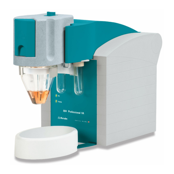
884 Professional VA front "Status" LED "On" LED Continuously on: instrument ready for oper- Illuminated if the 884 Professional VA is con- ation. Blinking regularly: instrument operat- nected to the power supply. ing. Blinking pattern "LED on a long time - off a short time - on a long time - off a short time, etc.": Standby potential is being... -
Page 19: Rear
For positioning the drip pan. may be present (such as electrode mercury) in fully automated mode. Rear Figure 2 884 Professional VA rear Temperature sensor connector (Temp.) Type plates For connecting a temperature sensor of the With serial number. type Pt1000. Two B sockets, 2 mm. - Page 20 "Controller" connector MSB connectors (MSB 1 to 4) For connecting to a PC with the viva com- Metrohm Serial Bus. For connecting dosing puter software installed. Mini DIN, 8-pin. devices (800 Dosino) and Remote Boxes. Mini DIN, 8-pin. Power socket ■■■■■■■■...
-
Page 21: Mme Measuring Head
With openings for inserting electrodes and For connecting the MME measuring head to tubing connections (see Figure 5, page 16). the connector plate of the measuring head arm (1- For connecting the electrodes and tubing (see Figure 4, page 14). ■■■■■■■■ 884 Professional VA... -
Page 22: Measuring Head Connector Plate And Measuring Head Insert
For connecting the inert gas supply (N For aspirating the measuring solution. Can Connected directly to the working electrode. be connected to one of the openings 24 - The tubing comes pre-installed. 27 (FEP tubing from 6.1829.070). ■■■■■■■■ 884 Professional VA... - Page 23 12 M6 threaded opening (TAP) With preinstalled tubing connection to With preinstalled tubing connection to opening 18 - gas outlet. threaded opening 17 - gas inlet to the tap- ping mechanism. 14 - 30: see next figure ■■■■■■■■ 884 Professional VA...
-
Page 24: Figure 5 Measuring Head Insert
(6.1824.000). tapping mechanism. 18 Opening 19 Opening With preinstalled tubing connection to For tubing connection to threaded opening threaded opening 11 (OUT) - gas outlet. 8 (PURGE) - gas inlet in the measuring solu- tion. ■■■■■■■■ 884 Professional VA... -
Page 25: Tubing Connector (Measuring Head Arm)
TAP, PURGE ing solutions. and N via the measuring head arm. M6 threaded opening (2) UNF 10/32 threaded opening (SMP) For connecting tubing for aspirating or add- For connecting a capillary for automated ing solutions. sample addition. ■■■■■■■■ 884 Professional VA... - Page 26 M6 threaded opening (1) M6 threaded opening (WASTE) For connecting tubing for aspirating or add- For connecting tubing for aspirating the ing solutions. measuring solution. M6 threaded opening (OUT) For pressure compensation in the measuring vessel. ■■■■■■■■ 884 Professional VA...
-
Page 27: Rde Measuring Head
With openings for inserting electrodes and For connecting the RDE measuring head to tubing connections (see Figure 9, page 22). the connector plate of the measuring head arm (1- For connecting the electrodes and tubing (see Figure 8, page 20). ■■■■■■■■ 884 Professional VA... -
Page 28: Measuring Head Connector Plate And Measuring Head Insert
M6 threaded opening (N M6 threaded opening (WASTE) With preinstalled stopper. Not applicable to For aspirating the measuring solution. Can RDE applications. be connected to one of the openings 24 - 27 (FEP tubing from 6.1829.070). ■■■■■■■■ 884 Professional VA... - Page 29 For voltammetric applica- ses. tions, not applicable to CVS analyses. 13 Guide roller 14 - 30: see next figure Transfers the rotary movement of the motor to the driving axle of the working electrode. ■■■■■■■■ 884 Professional VA...
-
Page 30: Figure 9 Measuring Head Insert
For tubing connection to threaded opening threaded opening 11 (OUT) - gas outlet. For 8 (PURGE) - gas inlet in the measuring solu- voltammetric applications, not applicable tion. For voltammetric applications, not to CVS analyses. applicable to CVS analyses. ■■■■■■■■ 884 Professional VA... -
Page 31: Tubing Connector (Measuring Head Arm)
M6 threaded opening (3) Is connected to the threaded openings TAP, For connecting tubing for aspirating or add- PURGE and N via the measuring head arm. ing solutions. For voltammetric applications, not applica- ble to CVS analyses. ■■■■■■■■ 884 Professional VA... - Page 32 M6 threaded opening (1) M6 threaded opening (WASTE) For connecting tubing for aspirating or add- For connecting tubing for aspirating the ing solutions. measuring solution. M6 threaded opening (OUT) For pressure compensation in the measuring vessel. ■■■■■■■■ 884 Professional VA...
-
Page 33: Setting Up The Instrument
CVS, follow the described procedure for the RDE measuring head (see Chapter 3.3, page 45). NOTE For equipping, we recommend placing the MME measuring head in the measuring head holder and only then inserting it onto measuring head arm. ■■■■■■■■ 884 Professional VA... -
Page 34: Figure 11 Removing The Stopper From The Pipetting Opening
2 Pull the slide lock (3-4) on the top of the measuring head cover towards you and, at the same time, tilt the measuring head cover to an angle of approx. 45° and remove it. Figure 12 Removing the measuring head cover ■■■■■■■■ 884 Professional VA... -
Page 35: Preparing The Mme Measuring Head
Insert the PTFE tubing for adding gas to the solution (6.1829.030) ■ through the opening (5-19). Pull the transparent inner tubing through as far as it will go. ■ Ensure that the green kink protection is protecting the entire piece ■ of tubing. ■■■■■■■■ 884 Professional VA... -
Page 36: Figure 13 Inserting The Gas Inlet
3.2 Equipping the MME measuring head Figure 13 Inserting the gas inlet Connect the tubing to the PURGE threaded opening (4-8) and ■ tighten it handtight. Finally, tighten the tubing nipple using the wrench provided ■ (6.2739.000). ■■■■■■■■ 884 Professional VA... -
Page 37: Figure 14 Connecting The Gas Inlet
(6.2739.000). In the process, ensure that the flexible shaft is not bent. Figure 15 Screwing in the flexible shaft Insert the stirrer into the opening (5-15) and press it down as far ■ as it will go. ■■■■■■■■ 884 Professional VA... -
Page 38: Figure 16 Inserting And Connecting The Stirrer
Screw the clamping screw for the flexible shaft to the drive shaft ■ using two wrenches (6.2739.000). In the process, ensure that the flexible shaft is not kinked. Figure 16 Inserting and connecting the stirrer ■■■■■■■■ 884 Professional VA... -
Page 39: Preparing Electrodes And Inserting Them In The Mme Measuring Head
Inserting stoppers 3.2.2 Preparing electrodes and inserting them in the MME measuring head The 884 Professional VA uses the three-electrode principle. The following electrodes are used: Multi-Mode Electrode pro (MME pro) as the working electrode (WE) ■ Reference electrode (RE) ■... - Page 40 Place an empty measuring vessel in the holder (1-3). ■ Carefully insert the working electrode into the opening (5-21) of ■ the measuring head insert. The bottom of the capillary must not touch the measuring head while being inserted. ■■■■■■■■ 884 Professional VA...
- Page 41 Observe the markings on the plugs, because the three cables must not be mixed up. Plug the electrode cable (4-7) with the WE marking on the plug onto the metal contact of the working electrode. ■■■■■■■■ 884 Professional VA...
-
Page 42: Figure 18 Connecting The Working Electrode
■■■■■■■■■■■■■■■■■■■■■■ 3.2 Equipping the MME measuring head Figure 18 Connecting the working electrode ■■■■■■■■ 884 Professional VA... -
Page 43: Figure 19 Connecting The Inert Gas Inlet
Adjust the needle valve in accordance with the instructions in the Multi-Mode Electrode pro document (8.110.8018XX) and the Elec- trodes in VA multimedia guide (A.717.0002). 6 Testing the electrode function Test the electrode function in accordance with the instructions in the Multi-Mode Electrode pro document (8.110.8018XX). ■■■■■■■■ 884 Professional VA... - Page 44 4 Place the reference electrode in the filled electrolyte vessel and screw it in place. The electrolyte solution that is displaced in the electrolyte vessel is forced out of the deaeration openings. ■■■■■■■■ 884 Professional VA...
-
Page 45: Figure 20 Assembling The Reference Electrode With The Electrolyte Vessel
Observe the markings on the plugs, because the three cables must not be mixed up. Plug the electrode cable (4-7) with the RE marking on the plug onto the metal contact of the reference electrode. ■■■■■■■■ 884 Professional VA... -
Page 46: Figure 21 Connecting A Reference Electrode
(6.1247.000): Together form the optionally available glassy carbon auxiliary electrode The Pt auxiliary electrode (6.0343.000) included in standard delivery can be inserted directly into the measuring head. The optionally available GC auxiliary electrode has to be put together first. ■■■■■■■■ 884 Professional VA... -
Page 47: Figure 22 Structure Of The Auxiliary Electrodes
In the event the GC rod breaks, the remaining part in the holder can be removed by pulling out the retaining ring (22-6). Insert the glassy carbon rod (22-7) through the retaining ring (22-6) into the electrode holder (22-5) as far as it will go. ■■■■■■■■ 884 Professional VA... - Page 48 Observe the markings on the plugs, because the three cables must not be mixed up. Plug the electrode cable (4-7) with the AE marking on the plug onto the metal contact of the auxiliary electrode. ■■■■■■■■ 884 Professional VA...
-
Page 49: Inserting The Mme Measuring Head
Proceed as follows to do this: 1 Tilt the measuring head arm up. CAUTION Do not apply pressure to the drive disk on the connector plate of the measuring head arm, as this could damage the stirrer motor. ■■■■■■■■ 884 Professional VA... -
Page 50: Connecting The Inert Gas Supply
For general polarography/voltammetry: 4.5 (w(N ) = 99.995%) ■ For analyses in organic solvents; for determinations that result in very high current strengths (such as for determining the smallest concentrations without preceding deposition) ■■■■■■■■ 884 Professional VA... -
Page 51: Figure 26 Gas Washing Glass
2 Connecting the inert gas inlet Connect one end of the PVC tubing (6.1801.080) on the N nip- ■ ple of the 884 Professional VA. Connect the other end of the PVC tubing (6.1801.080) to the ■ inert gas bottle connection. -
Page 52: Installing The Measuring Head Cover
Make sure that your fingers do not get caught between the meas- uring head cover and the measuring head. Fold back the measuring head cover and gently push it in place. The measuring head cover must snap into place with an audible click. ■■■■■■■■ 884 Professional VA... -
Page 53: Equipping The Rde Measuring Head
Proceed as follows: 1 Tilt the measuring head arm up. CAUTION Do not apply pressure to the drive disk on the connector plate of the measuring head arm, as this could damage the stirrer motor. ■■■■■■■■ 884 Professional VA... -
Page 54: Figure 29 Do Not Touch The Drive Disk
The measuring head must snap into place with an audible click. Figure 30 Inserting the measuring head 3 Remove the stopper from the pipetting opening. ■■■■■■■■ 884 Professional VA... -
Page 55: Figure 31 Removing The Stopper From The Pipetting Opening
4 Pull the slide lock on the top of the measuring head cover towards you and, at the same time, tilt the measuring head cover to an angle of approx. 45° and remove it. Figure 32 Removing the measuring head cover ■■■■■■■■ 884 Professional VA... -
Page 56: Connecting The Gas Inlet
Insert the PTFE tubing for adding gas to the solution (6.1829.030) ■ through the opening . Pull the transparent inner tubing through as far as it will go. ■ Ensure that the green kink protection is protecting the entire piece ■ of tubing. ■■■■■■■■ 884 Professional VA... -
Page 57: Figure 33 Inserting The Gas Inlet
■■■■■■■■■■■■■■■■■■■■■■ 3 Installation Figure 33 Inserting the gas inlet Connect the tubing to the PURGE threaded opening (4-8) and ■ tighten it hand-tight. Finally, tighten the tubing nipple using the wrench provided ■ (6.2739.000). ■■■■■■■■ 884 Professional VA... -
Page 58: Preparing Electrodes And Inserting Them In The Rde Measuring Head
Connecting the gas inlet 3.3.2 Preparing electrodes and inserting them in the RDE measuring head The 884 Professional VA uses the potentiostatic three-electrode principle. The following electrodes are used: Rotating disk electrode (RDE) as working electrode (WE) ■ Reference electrode (RE) ■... -
Page 59: Figure 35 Removing The Protective Cap From The Electrode Tip
Insert the working electrode into the opening (9-21) of the measur- ing head insert. Make sure that the pin on the lower part of the driving axle is posi- tioned in the opening (9-15) of the measuring head insert. ■■■■■■■■ 884 Professional VA... -
Page 60: Figure 37 Working Electrode, Installed
■ wheel of the driving axle. Figure 38 Fastening the drive belt NOTE Make sure that the drive belt does not rub against the driving axle or surrounding components (tubing, cables, etc.). ■■■■■■■■ 884 Professional VA... -
Page 61: Figure 39 Connecting The Working Electrode
Figure 39 Connecting the working electrode 3.3.2.2 Reference electrode (RE) The reference electrode consists of the following two articles: Reference electrode filled with reference electrolyte (e.g. 6.0728.130) ■ Electrolyte vessel filled with bridge electrolyte (e.g. 6.1245.010) ■ ■■■■■■■■ 884 Professional VA... -
Page 62: Figure 40 Assembling The Reference Electrode With The Electrolyte Vessel
The electrolyte solution that is displaced in the electrolyte vessel is forced out of the deaeration openings. Figure 40 Assembling the reference electrode with the electrolyte vessel 5 Rinse the installed reference electrode with ultrapure water. ■■■■■■■■ 884 Professional VA... - Page 63 Observe the markings on the plugs, because the three cables must not be mixed up. Plug the electrode cable (8-7) with the RE marking on the plug onto the metal contact of the reference electrode. ■■■■■■■■ 884 Professional VA...
- Page 64 Observe the markings on the plugs, because the three cables must not be mixed up. Plug the electrode cable (8-7) with the AE marking on the plug onto the metal contact of the auxiliary electrode. ■■■■■■■■ 884 Professional VA...
-
Page 65: Installing The Measuring Head Cover
■■■■■■■■■■■■■■■■■■■■■■ 3 Installation 3.3.3 Installing the measuring head cover For the procedure, see Chapter 3.2.5, page 44. ■■■■■■■■ 884 Professional VA... -
Page 66: Connecting Instruments Electrically
Connect the power cord to the power grid. ■ 3.4.2 Connecting the 884 Professional VA The 884 Professional VA is connected to the PC with the supplied control- ler cable. Connecting the PC Proceed as follows: 1 Connect the controller cable (6.2151.000) to the "Controller" con- nector of the 884 Professional VA. - Page 67 2 Connect the USB plug of the controller cable to an available USB connector on the PC. Initializing the 884 Professional VA in viva Proceed as follows: 1 Start viva. The following dialog window is displayed: 2 Click on Yes.
- Page 68 ■■■■■■■■■■■■■■■■■■■■■■ 3.4 Connecting instruments electrically 3 Change the suggested instrument name if required. 4 Confirm with OK. The instrument will be automatically listed in the device table of the Configuration program part. ■■■■■■■■ 884 Professional VA...
- Page 69 The 884 Professional VA is operated exclusively via the viva computer software. You can find information on operating viva in the online help and in the VA and CVS tutorials. Proceed as follows for the initial start-up of the 884 Professional VA: Preparing the system for starting up WARNING Uncontrolled splashing of reagents Splashing reagents may result in injuries.
- Page 70 Calibrator of the detailed man- ual. In viva, proceed as follows: 1 Select the 884 Professional VA in the device table of the Configura- tion section of the program. 2 In the device table, click on the Edit button and select Properties..
- Page 71 The calibration certificate is available online. Go to http:// www.metrohm.com/en/support-and-service/certificate-finder enter the serial number of the calibrator and download the certifi- cate. 5 If required, adjust the settings on the Calibrator tab (e.g. Message or Action). ■■■■■■■■ 884 Professional VA...
-
Page 72: Replacing The Measuring Head
1 Tilt the measuring head arm up. 2 Hold the measuring head with both hands, push the metal clip on the bottom of the measuring head arm upwards and, at the same time, pull the measuring head away. ■■■■■■■■ 884 Professional VA... -
Page 73: Figure 41 Removing The Measuring Head
When using a Multi-Mode Electrode pro along with additional auto- mated aspiration of the measuring solution, watch for traces of mer- cury in the indicated connector (WASTE) when removing the MME measuring head. Remove any traces using a mercury drop catcher (6.2406.000). ■■■■■■■■ 884 Professional VA... -
Page 74: Figure 43 Do Not Touch The Drive Disk
If the measuring head arm is folded down without due care, this may result in injuries to the hands. Make sure that your fingers do not get caught between the meas- uring head arm and the instrument housing. Lower the measuring head arm again. ■■■■■■■■ 884 Professional VA... -
Page 75: Performing A Dummy Cell Test
The curve must be linear. ■ At –2.0 V, the current should be –1.67 mA ± 0.33 mA. ■ At +2.0 V, the current should be +1.67 mA ± 0.33 mA. ■ ■■■■■■■■ 884 Professional VA... -
Page 76: Figure 44 Dummy Cell Test - Ideal Curve Progression
5.2 Performing a Dummy cell test Figure 44 Dummy cell test – Ideal curve progression 5 If the resulting curve is not consistent with this representation and the problems with the determinations persist, contact the local Met- rohm Service. ■■■■■■■■ 884 Professional VA... -
Page 77: List Of Faults
Check the tubing connections and the four- automatically: Tubing con- way micro dosing tip and replace if necessary. nections are not sealed or the four-way micro dosing tip for adding standard sol- utions is not immersed in the measuring solution. ■■■■■■■■ 884 Professional VA... -
Page 78: 884 Professional Va For Va Trace Analysis
Apply fresh solution; use water from a differ- tions in use (water, electro- ent source. lyte, VMS, etc.) has become contaminated. 6.1.2 884 Professional VA for VA trace analysis Problem Cause Remedy A peak is not found The peak is not within the... - Page 79 This can head. allow nitrogen to escape at the connection. The seals at the transitions Contact Metrohm Service for how to proceed. are too old. Curves have a large The needle is not adjusted. Adjust the needle (see the Multi-Mode ■...
- Page 80 (with HMDE). No drops form at the capil- Check the nitrogen connection and pres- ■ lary. sure. Ensure that the measuring head is attached ■ correctly and locked in place. ■■■■■■■■ 884 Professional VA...
- Page 81 The MME pro or compo- Check the MME pro. ■ jumps are present in nents of the MME pro have If necessary, replace the capillary and nee- ■ the voltammogram. been damaged. dle (see the Multi-Mode Electrode pro document (8.110.8018XX)). ■■■■■■■■ 884 Professional VA...
- Page 82 Shorten the deposition time in the voltam- ■ metry command under Potentiostatic pretreatment. Carry out the determination using polarog- ■ raphy at the DME instead of stripping vol- tammetry. Use less of the sample amount or dilute the ■ sample. ■■■■■■■■ 884 Professional VA...
- Page 83 The incorrect peak has Carry out spiking with a standard solution ■ been evaluated. to check whether the correct peak has been evaluated. Enter the characteristic potential in viva ■ again and recalculate the results. ■■■■■■■■ 884 Professional VA...
- Page 84 Oxygen is interfering with We recommend deaerating with nitrogen for the measurement. The at least 5 min or approximately 10 min for sample has not been dea- alkaline solutions. erated sufficiently. ■■■■■■■■ 884 Professional VA...
- Page 85 The concentration to be Reduce the deposition time. ■ determined is substantially If the application permits, change the elec- ■ higher than assumed. trode type (e.g. HMDE to SMDE or DME). Reduce the sample volume. ■ ■■■■■■■■ 884 Professional VA...
-
Page 86: 884 Professional Va For Cvs
Mode Electrode pro document (8.110.8018XX). The tapping mechanism is not functioning ■ correctly: Check the tapping of the drops. 6.1.3 884 Professional VA for CVS Problem Cause Remedy Conditioning takes a The reference electrode has After maintenance of the reference electrode, long time. - Page 87 However, for CVS analyses, replace the reference electrolyte every other day and the bridge electrolyte every day. After replacing the reference electrolyte, wait at least 20 minutes (preferably 1 - 2 h) until the potential has reached equilibrium. ■■■■■■■■ 884 Professional VA...
- Page 88 The concentration of the Add a larger volume or use the RC calibration standard solution or the technique instead of DT. sample is too low. ■■■■■■■■ 884 Professional VA...
-
Page 89: Tubing Lengths In The Measuring Head Arm
A standby potential is being applied to the "LED on a long electrodes. Do not remove the measuring head time - off a short or the electrode cables in this instrument status. time - on a long time - off a short time…" ■■■■■■■■ 884 Professional VA... - Page 90 The PDF file with the accessories data will be created. NOTE When you receive your new instrument, we recommend downloading the accessories list from the Internet, printing it out and keeping it together with the manual for reference purposes. ■■■■■■■■ 884 Professional VA...
- Page 91 ■■■■■■■■■■■■■■■■■■■■■■ Index Index Start-up ......61 RDE measuring head 884 Professional VA Troubleshooting ....69 Instrument status ...... 81 Parts ........19 See also "RDE measuring head" ........... 19 Auxiliary electrode RDE measuring head connector Blinking pattern ....81 Connect ....... 40, 56 plate Instrument status ....
Need help?
Do you have a question about the 884 Professional VA and is the answer not in the manual?
Questions and answers