Table of Contents
Advertisement
Quick Links
High Volume Air Sampler
O P E R A T I O N M A N U A L
This operation manual describes precautions that are important for preventing accidents as
well as the procedures used to handle the product.
To ensure safety, read this operation manual and the attached warranty thoroughly before
use, and use the product correctly.
After reading this operation manual and the warranty, keep them in a safe place where they
can be referred to at any time.
Thank you for purchasing this product.
CODE 080130-1200
080130-1201
080130-1203
Advertisement
Table of Contents

Related Manuals for Sibata HV-RW

Summary of Contents for Sibata HV-RW
- Page 1 CODE 080130-1200 080130-1201 080130-1203 High Volume Air Sampler O P E R A T I O N M A N U A L Thank you for purchasing this product. This operation manual describes precautions that are important for preventing accidents as ...
-
Page 2: Table Of Contents
Contents Before Use ........................3 Safety Precautions ......................4 Product Overview ......................7 Features ........................... 7 Names of Parts ........................ 8 Installation ........................10 Conveyance ......................10 Installation Procedure ..................... 11 Wiring Methods ....................... 12 Attaching the Shuttle Tube ..................13 Attaching the Filter Case .................. -
Page 3: Before Use
If you discover any errors or omissions, however, please contact your Sibata representative. The copyright of this operation manual belongs to Sibata Scientific Technology Ltd. The reproduction of all or part of this operation manual without prior written permission from Sibata Scientific Technology Ltd. -
Page 4: Safety Precautions
Safety Precautions The precautionary information that appears in this operation manual is for ensuring that the product is used safely and for preventing injury to you and other people and damage to equipment. It is all important for ensuring safety and so be sure to read it thoroughly before using the product and observe it during use. - Page 5 When the abnormality is judged to be caused by this product, turn the power switch OFF, disconnect the power plug and contact the distributor or your Sibata representative. Do not use this product in an abnormal state or allow it to be dismantled for repair by non-service personnel.
- Page 6 might cause malfunction. Should foreign objects get inside this product, immediately turn the power switch OFF, disconnect the power plug, and contact the distributor or your Sibata representative. The operating temperature and humidity ranges of this product are 0 to 40 °C and 10 to ...
-
Page 7: Product Overview
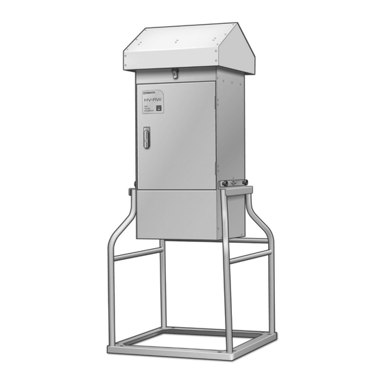
Product Overview The HV-RW are samplers intended for outdoor use. These products sample suspended dust in the open face, and provide quantitative analysis of dust concentration and composition. High-accuracy flow rate control is provided by a differential pressure detection system, and instantaneous and cumulative flow rate values are displayed digitally. -
Page 8: Names Of Parts
Names of Parts Sampler (1) Door (7) Through pipe/shuttle tube (2) Flush lever handle (8) Clamps (3) Snap fastener (9) Mini knobs (4) Canopy (10) Cable stopper (5) Control unit HV-RW-K1 (11) Power cable (6) Hopper (12) Legs - 8 -... - Page 9 Control Unit (1) Power switch (5) USB (B) connector (2) Circuit protector (6) Flow meter suction port (3) Touch panel (7) Atmospheric temperature sensor connector (4) [START/STOP] button (8) Atmospheric pressure sensor tube Hopper (1) Hopper (6) Hopper top stage guide (2) Perpendicular bolt (7) Quick clamp knob (3) Sliding cover...
-
Page 10: Installation
Installation Conveyance Be sure to check that the hopper is fastened as next sentence. Ensure that the hopper is fitted into the hopper top stage fixing block and that the hole is sealed with the sliding cover. Then tighten the hopper fixing screw. Check that the quick clamp knobs are securely fastened on the screws at the quick clamp knob storage area. -
Page 11: Installation Procedure
Installation Procedure Two or more people are required to move this product. Install the product on a flat surface. Avoid high moisture, high humidity sites, sites in proximity to flames or heat sources, and extremely dusty sites. Be sure to use a rope to keep the product from tipping over. The product is provided with 8 anchor bolt holes at the bottom of the legs, and 4 rope fixing holes at the top of the legs (rotation axis part). -
Page 12: Wiring Methods
Wiring Methods Use in Japan Use a single phase 100 V power supply (90 V to 132 V can be used.). Be sure to ground this product. When using this product outdoors, ensure that the electrical outlet and/or extension cable are waterproofed. -
Page 13: Attaching The Shuttle Tube
Attaching the Shuttle Tube Mount a ferrule gasket on the shuttle tube. Then attach the shuttle tube on the flow meter suction port, and fasten it with a clamp. Place a ferrule gasket on the shuttle tube. Be careful of the shuttle tube orientation. If it is attached upside down, the urethane holder inside might fall, and there is a risk that the glass will break. -
Page 14: Attaching The Filter Case
Attaching the Filter Case Ensure that a filter is mounted in the filter case. Then put the filter case to the hopper. Mount washers on the perpendicular bolts. Then attach the quick clamp knobs and fasten them. If a quick clamp knob is fastened too tightly, it may end up spinning freely, and there is a risk of damage to the quick clamp knob and the perpendicular bolt. -
Page 15: Capability Of This Product
Tube Through pipe: HV-RW for dust collection standard accessory Shuttle tube: HV-RW for dioxins standard accessory. It contains a urethane holder (glass tube), containing a 90 mm diameter polyurethane foam that is used to perform dioxin sampling. Filter 8" × 10" filters can be mounted. -
Page 16: Touch Panel
Touch Panel This product is equipped with a touch panel liquid crystal display. Operations can be performed by touching the display directly. Press the [START/STOP] button to start sampling. Touch keys are arranged at various points on the respective touch panel screens. Operations can be performed by touching them. -
Page 17: Main Screen
Main Screen When the power is first turned ON, "System Initializing" will be displayed for 5 seconds. The screen then changes to the following screen: Model name Serial number Software version If you touch the screen while this screen is displayed, or simply wait approximately 5 seconds, the system will proceed to the main screen, shown below. -
Page 18: Sampling Method
Sampling Method Setting the Flow Rate Touch the numerical region of the flow rate settings directly to proceed to the flow rate setting screen, where the flow rate can be set. In the flow rate setting screen, press the numerical keys to enter the desired flow rate. -
Page 19: Setting The Operation Start Timer
Setting the Operation Start Timer Press the characters in the operation start timer area to switch between the delay timer and the clock timer. The delay timer, shown onscreen as DELAY , starts the operation after a certain period of time has elapsed. The clock timer, shown onscreen as CLOCK , starts the operation at a specific hour and minute. - Page 20 Press the numbers next to CLOCK to proceed to the start time setting screen, where the starting time can be set. If the numbers next to CLOCK show a time earlier than the present time, when the numbers are pressed, the next full hour after the present time will be shown, and the system will proceed to the start time setting screen.
-
Page 21: Setting The Operation End Timer
Setting the Operation End Timer Press the characters in the operation end timer area to switch between the sampling timer and the volume timer. The sampling timer, shown onscreen as TIMER, ends the operation after the configured period of time has elapsed. The volume timer, shown onscreen as VOL., ends the operation when the configured cumulative flow rate has been reached. - Page 22 Press the numbers next to VOL. to proceed to the ending cumulative flow rate setting screen, where the ending cumulative flow rate can be set. Entering 0.0 m will engage manual operations, in which pressing the [START/STOP] button will stop operations. The system will automatically stop however when 99,999.9 m is reached.
-
Page 23: Starting Operations
Starting Operations In the main screen, confirm the setting conditions. In the example in the figure below, the set flow rate is 1,000 L/min, operations start 1 hour later, and operations continue for 8 hours. Press the [START/STOP] button to start operations. The [START/STOP] button must be pressed to start operations, even if the timer has been set. -
Page 24: During Operation
During manual operation, as soon as the [START/STOP] button is pressed, the blower will run, and the sampler will start operating. When the timer has been set, the following screen appears, and the system remains in standby until the configured date and time. During standby, the message "WAIT" will blink onscreen. -
Page 25: Error Displays
Error Displays If an error occurs during operation, this product will log the error (See page 32.). Unless the error involves the blower however, the blower will not stop, and operation will continue. If an error occurs, it will be indicated onscreen. Error Item Internal battery FL: Flow rate error... -
Page 26: Power Outages
Power Outages If a power outage occurs during operation, the product will turn off and stop operating. The remaining sampling will continue after power is restored. E.g.) If an 8 hour sampling period has been set, and a 1 hour power outage occurring during this time, sampling will be delayed by 1 hour, but the full 8 hours of sampling will be completed. -
Page 27: Mode Display
Mode Display In the main screen and other screens, press MODE to view environmental information. The displayed items will differ before and after blower operation. Prior to Operation (before the [START/STOP] button is pressed) Press MODE to toggle in sequence between the screens shown below. Press to return to the main screen. - Page 28 During Standby (after the [START/STOP] button is pressed but before the blower runs) Press MODE to toggle in sequence between the screens shown below. Press to return to the main screen. MODE Atmospheric temperature Atmospheric pressure During Operation (blower operating) Press MODE to toggle in sequence between the screens shown below.
-
Page 29: Menu
Menu In the main screen, press MENU to display the menu shown in the following figure. Sampling data Toggling flow rate correction method Time setting Error setting Screen setting ESC key Serial No. setting Calibration mode Sampling data ··········· Displays the last 5 sets of sampling data. (See page 30.) Time setting ··············... -
Page 30: Sampling Data
Sampling Data In the main screen, press SAMP. DATA to review previous sampling data (up to the last 5 sets). Press 1 to review the most recent sampling data. The most recent 5 sets can be viewed by pressing the other numbers respectively. If no sampling data exists, the message "NO DATA"... - Page 31 The sampling data is shown over a total of 4 pages. Press and to toggle between the pages. Sampling start time Sampling time Cumulative flow rate Flow rate settings Average flow rate Flow rate correction method ...
-
Page 32: Detailed Error Display
Detailed Error Display TRBL is displayed when an error has occurred. Press TRBL to view detailed error information. The error details can be viewed as shown below. The last 5 errors are logged in sequence from the oldest, and can be viewed by pressing the respective number keys. The 6th and subsequent errors are not logged. -
Page 33: Setting The Time
Setting the Time In the menu screen, press RTC SET to display the screen in the figure at right. From the left, the display shows the year, month, day, hour, minute, and second. Press the respective numerical regions to proceed to the numerical value entry screen. -
Page 34: Setting The Screen
Setting the Screen In the menu screen, press DISPLAY to display the screen setting screen in the figure at right. Press + and or - keys of “Brightness” to adjust the brightness for screen. When settings are complete, press ESC to return to the menu screen. -
Page 35: Setting The Error
Setting the Error In the menu screen, press TRBL SET to display the error setting screen as in the figure below. Press the respective numerical regions to proceed to the numerical value entry screen. Set the respective threshold values. Press to return to the menu screen. -
Page 36: Calibration Mode
Calibration Mode In the menu screen, press CAL to switch to calibration mode. This section only describes the operating methods in the calibration mode. When performing an actual calibration, see the section on calibration methods. (See page 38.) SPAN key ZERO key Flow rate Atmospheric pressure... -
Page 37: Leak Check
Leak Check Press LEAK CHECK to switch to leak check mode. Press to return to the calibration screen. For the leak check, prepare an HV rectangular rubber plate (sold separately). Attach it to the filter case using the same procedures as for attaching filters, and seal off the sampler's suction port. -
Page 38: Calibration Methods
An optionally available standard flow meter can be attached to the sampler's intake side. Calibration at the work site is simplified by using Sibata OF-1S orifice flow meter (sold separately) as the standard flow meter (Rectangular adapter for orifice flow meter is required. -
Page 39: Atmospheric Pressure Calibration
Atmospheric Pressure Calibration Calibration can similarly be performed with respect to the atmospheric pressure sensor. Prepare a standard pressure gage, remove the atmospheric pressure sensor tube, and connect the gage. 1. In the calibration mode, set the atmospheric pressure span value to 1.000, and return the zero value to 0.000. -
Page 40: Flow Rate Correction Method
HyperTerminal can be used. A special USB driver is required for communications. The USB driver can be downloaded from Sibata website: (http://www.sibata.co.jp/technology/technology-27640/) In addition, please refer to the online manual available at Sibata website for details on communications commands. - 40 -... -
Page 41: Maintenance
Maintenance Periodic maintenance is required in order to extend the life of this product. When cleaning the product, use dry cloths and thoroughly wrung out damp cloths. The stainless steel parts of the sampling line (each metal part of Hopper, Shuttle tube or Through pipe, Flow meter suction port) may be wiped clean with acetone. -
Page 42: Troubleshooting
Troubleshooting If a problem occurs during use, promptly stop using the oven. If the error was caused by a product failure, please do not operate the unit again request for repair. In some cases, errors may be caused by something other than a malfunction. Before requesting repair, verify the following. -
Page 43: Main Specifications
Main Specifications Product Code 080130-1201 080130-1203 Model HV-RW for aerosol HV-RW for dioxins Standard Suction Flow 100 or 700 L/min (quartz fiber filter + polyurethane foam, 2) Rate 566, 1000 L/min (glass fiber filter) Configurable Flow Rate 100 to 1200 L/min... -
Page 44: Spare Parts
(not including urethane) 080130-0973 Filter case (standard accessory) For 8" × 10" rectangular filters 080130-0994 Clamp For shuttle tube, no lock 080130-1200 Control unit HV-RW-K1 for HV-RW 080130-1205 Shelter HV-RW-S1 for HV-RW 080130-1206 Hopper for HV-R/HV-RW Consumables Product Code Name of Part... -
Page 45: Warranty And Repair
For details of repair after the Warranty has expired, contact the distributor where you purchased the product. The product shall be repaired for a fee only if Sibata judges that repair shall restore its functions, and its functions can be sustained in the future only in accordance with specified methods of use. -
Page 46: Disposal Of The Product
(POM). Inquiries If you have any questions about this product, or if there is any other way in which we can be of assistance, contact the distributor or your Sibata representative. 21.08.17 K (03) - 46 -... -
Page 47: Trouble Notification Sheet
Please fill in this sheet in as much detail as possible. Also, attach this sheet when asking for repair. High Volume Air Sampler HV-RW Trouble Notification Sheet If the sampler malfunctions, make a copy of this sheet, fill it in and contact the distributor where you purchased the product. - Page 48 Note) Shape, dimensions, specifications, and other product information are subject to change without notice in the interest of product improvement to the extent that product functions and applications will not be impaired.
Need help?
Do you have a question about the HV-RW and is the answer not in the manual?
Questions and answers